• Scam Alert. Members are reminded to NOT send money to buy anything. Don't buy things remote and have it shipped - go get it yourself, pay in person, and take your equipment with you. Scammers have burned people on this forum. Urgency, secrecy, excuses, selling for friend, newish members, FUD, are RED FLAGS. A video conference call is not adequate assurance. Face to face interactions are required. Please report suspicions to the forum admins. Stay Safe - anyone can get scammed.
  • Several Regions have held meetups already, but others are being planned or are evaluating the interest. The Ontario GTA West area meetup is planned for Saturday April 26th at Greasemonkeys shop in Aylmer Ontario. If you are interested and haven’t signed up yet, click here! Arbutus has also explored interest in a Fraser Valley meetup but it seems members either missed his thread or had other plans. Let him know if you are interested in a meetup later in the year by posting here! Slowpoke is trying to pull together an Ottawa area meetup later this summer. No date has been selected yet, so let him know if you are interested here! We are not aware of any other meetups being planned this year. If you are interested in doing something in your area, let everyone know and make it happen! Meetups are a great way to make new machining friends and get hands on help in your area. Don’t be shy, sign up and come, or plan your own meetup!

How Not to Produce a Simple Wood Pattern

carrdo

Well-Known Member
Hi All,

Well, it started off very badly.

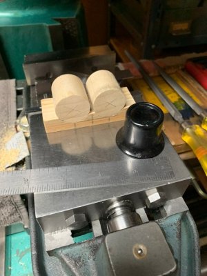
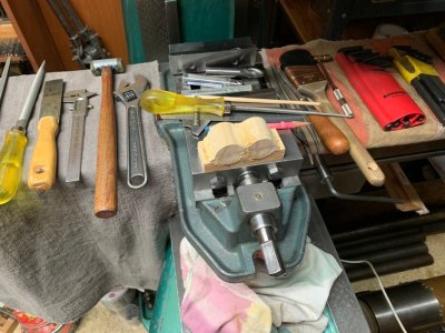
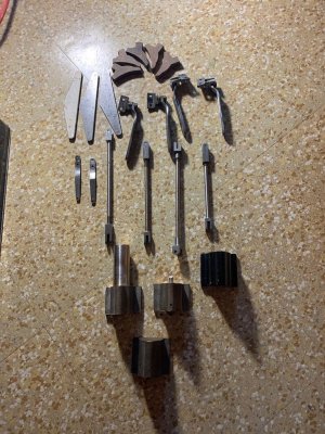
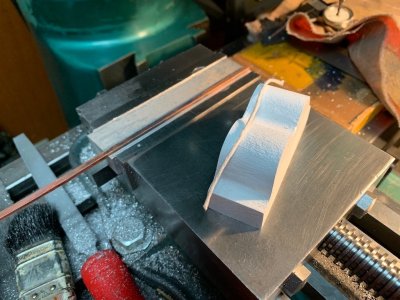
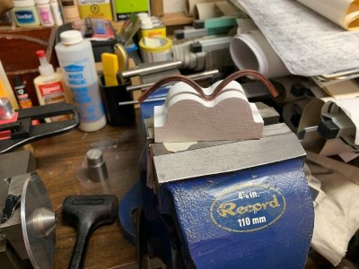
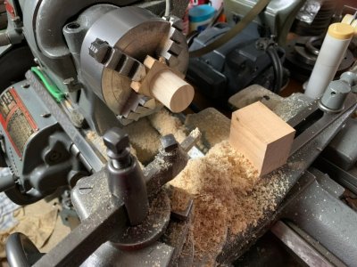
As I had the right (odd size commercial hardwood dowel of approx.1-3/32" dia) I said right, I will use that for the two cylinder pieces. So, I got to the stage shown in photo 30 when I started to measure things more closely and I discovered that this "round" dowel was really egg shaped and by a lot!
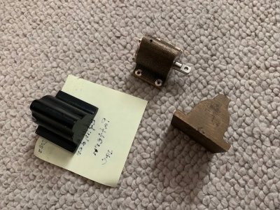
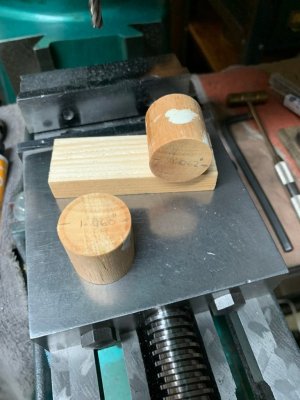
And, as well, after further calculations on how deep the two cylinder cutouts in the base block needed to be, the base block turned out to be too thin so scrap everything shown and start over again.

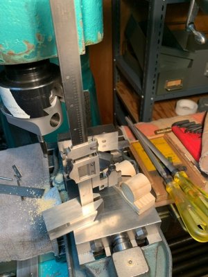
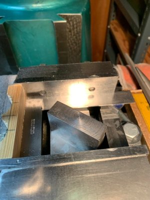
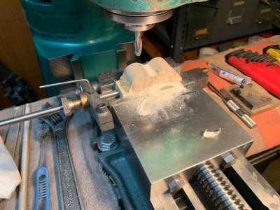
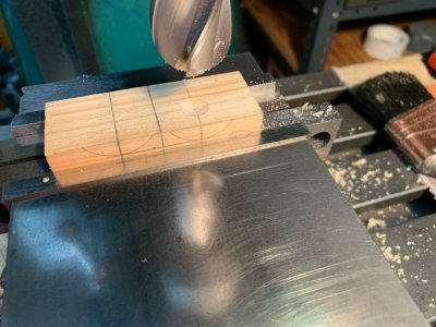
So, square up a new thicker base block and then carefully layout where the two cylinders needed to be (1-3/16" centre to centre with a 9/32" deep cutout). And, in addition, since everything needed to be centered lengthwise, this took a while.

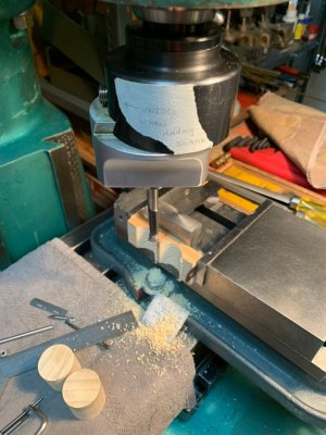
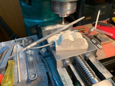
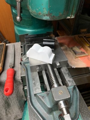
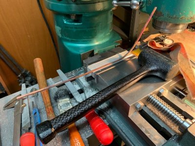
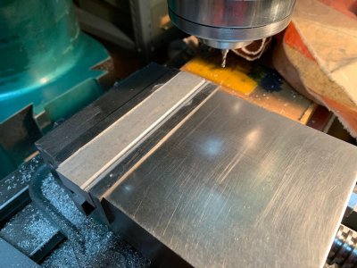
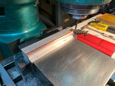
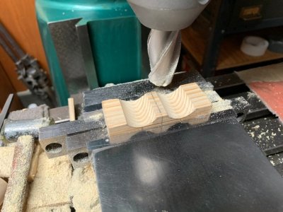
To rough out the two cylinder cutouts, I had a 1" dia. ball end mill and end mill holder. This was spotted on each cylinder centre line in turn as shown in photos 33, 34. Because the base block wood was just some unknown (a no, no) scrap wood which I had, I had to proceed very slowly and cautiously so as not to break the edges of the wood when the end mill entered and exited the piece. Some very minor splintering did occur but nothing which could not be fixed.

The only casualty; a lot of lost time doing everything the hard way again.

to be continued.
 

Attachments

  • 30 Fools Rush In Where....jpeg
    30 Fools Rush In Where....jpeg
    125.3 KB · Views: 8
  • 31 Re-turning the Two Cylinder Pieces.jpeg
    31 Re-turning the Two Cylinder Pieces.jpeg
    167.3 KB · Views: 6
  • 32 Base Block and Cylinder Components.jpeg
    32 Base Block and Cylinder Components.jpeg
    166.8 KB · Views: 4
  • 33 Locating a Cylinder Recess in the Base Block.jpeg
    33 Locating a Cylinder Recess in the Base Block.jpeg
    124.6 KB · Views: 4
  • 34 After Ball End Mill Milling.jpeg
    34 After Ball End Mill Milling.jpeg
    134.3 KB · Views: 8
Hi All,

To finish the cutouts in the base block, I switched to a boring head tool as seen in photo 35. To ensure everything remained square in both planes, I used the setup shown in photo 36. Afterwards, I checked the accuracy of the work and to my surprise the vernier height gauge shows both cylinder heights dead equal and the spacing was that way also.

Again, the only casualty was the amount of time taken and the fancy machining involved.

to be continued.
 

Attachments

  • 38 After Machining.jpeg
    38 After Machining.jpeg
    130.1 KB · Views: 11
  • 37 Checking  Cylinder Height after Machining the Base Block.jpeg
    37 Checking Cylinder Height after Machining the Base Block.jpeg
    142.5 KB · Views: 10
  • 36 The Setup Used to Maintain Square.jpeg
    36 The Setup Used to Maintain Square.jpeg
    119.8 KB · Views: 12
  • 35 Finished Recesses Using a Boring Head.jpeg
    35 Finished Recesses Using a Boring Head.jpeg
    139.7 KB · Views: 13
Hi David,

This will be the new double steam or air brake cylinder pattern for my 3/4" scale Hoffman NYC Hudson live steam locomotive. I now have the design for this and Carl Hoffman never had the casting for it. The original Hoffman brake cylinder drawing shows a single cylinder only which is based on a UK (appears to be from a Don Young) design.

The Hoffman brake cylinder drawing, as originally supplied, leaves much to be desired and is not prototype for either the NYC Hudson or for North American practice.

I will have to make a new model print to suit what I am producing as well.
 
Last edited:
Hi All,

Pushing on to where I am now.

The two cylinder pieces were first glued to the base block cutouts with some white glue letting the glue dry for about 24 hours and then the contour fillets were added in small thin incremental layers (approx. 4 in total). I let the filler dry for at least 24 hours before adding the next layer. I used standard plastic wood because it was cheap but in retrospect I maybe should have used something better like Bondo.

The next mistake made was to belt sand in the pattern draft (3 degree taper) on each long side. Don't do this as then it becomes very difficult to hold the partially made pattern straight in the vise for all of the contouring operations. Because of this, I had to keep reversing the tilted pattern in the vise after each pass of the ball end mill to end up with a straight cut.

Contouring the pattern plastic wood fillets and contours and blending them in to produce a seamless curve was undertaken using various diameter ball end mills and then finishing the continuous curves by very careful riffler and regular filing. It was quite concentrated and tense work as I had never attempted to do it this way before. The plastic wood, even in its hardened state, is quite weak and turns into a fine soft powder under end milling. I ran the mill at its highest speed and took only very light cuts (0.003" DOC) while feeding the end mill VERY slowly across the work taking particular care when entering or exiting the workpiece. Even so, there was some minor fracturing of the plastic wood filler at the sharp side edges which were then patched up and left to harden. This is where I think something like Bondo would have worked better. For the two cylinder side fillets the pattern piece was tilted 3 degrees (and sometimes more) in the vise using the reversal method to achieve a straight across cut to remove almost all of the excess fillet material and then blend it all in with careful hand filing.

Still have the all sides final draft to do.

As welI, I will try to harden the plastic wood fillets and contours (before the final shellac coating is applied and painting) to prevent damage in these areas when sand is rammed around the pattern as the plastic wood filler remains quite soft and weak.

Live and learn.

to be continued.
 

Attachments

  • 39 Looks Quite a Mess after Several Filler Applications.jpeg
    39 Looks Quite a Mess after Several Filler Applications.jpeg
    162.2 KB · Views: 8
  • 40 Pattern Draft Belt Sanding (don't do this at this stage).jpg
    40 Pattern Draft Belt Sanding (don't do this at this stage).jpg
    139.1 KB · Views: 7
  • 42 The Start of Contouring by Ball End Milling.jpg
    42 The Start of Contouring by Ball End Milling.jpg
    170.8 KB · Views: 6
  • 43 After Ball End Milling and Radii Blending by Delicate Filing.jpg
    43 After Ball End Milling and Radii Blending by Delicate Filing.jpg
    171.3 KB · Views: 9
Back
Top