Wow! What a clear and unambiguous description of my problem! I followed this with complete understanding - apart from knowing what the heck a screw anchor looks like. Its function is now clear enough - the screw itself should NOT move lengthwise - it needs to be held in place so it just rotates - and in doing that, moves the table because it passes through the threaded nut. Clear enough. Taken with Peter's excellent encouragement to disassemble at least the front part of this mechanism, I might just take a close look and see if there is some sort of an anchor that needs to be tightened, or perhaps replaced if it appears broken. I am thinking tightening it is a real possibility because this problem did not happen suddenly like it might have done if a part broke apart. Many thanks for the advice and encouragement.I'm still betting it's the screw anchor that has the slop in it. Fix the anchor and the problem will be gone.
Put another way, the screw itself should not move axially at all. Only the perceived motion of the screw threads appear to move as it is turned. But the threads shouldn't really move axially they should stay fixed by the screw anchor and the screw should only rotate. This is more easily seen by putting some paint on the screw threads. As the screw is turned, it looks like it's moving axially, but it isn't. If you watch the paint, it stays put and doesn't move axially. The fact that this gap appears and can go away at the crack interface demonstrates that the screw is moving axially when it shouldn't.
If you fix the screw anchor, which is usually at one end or the other of the screw, most of your problem should go away.
-
Scam Alert. Members are reminded to NOT send money to buy anything. Don't buy things remote and have it shipped - go get it yourself, pay in person, and take your equipment with you. Scammers have burned people on this forum. Urgency, secrecy, excuses, selling for friend, newish members, FUD, are RED FLAGS. A video conference call is not adequate assurance. Face to face interactions are required. Please report suspicions to the forum admins. Stay Safe - anyone can get scammed.
-
Several Regions have held meetups already, but others are being planned or are evaluating the interest. The Calgary Area Meetup is set for Saturday July 12th at 10am. The signup thread is here! Arbutus has also explored interest in a Fraser Valley meetup but it seems members either missed his thread or had other plans. Let him know if you are interested in a meetup later in the year by posting here! Slowpoke is trying to pull together an Ottawa area meetup later this summer. No date has been selected yet, so let him know if you are interested here! We are not aware of any other meetups being planned this year. If you are interested in doing something in your area, let everyone know and make it happen! Meetups are a great way to make new machining friends and get hands on help in your area. Don’t be shy, sign up and come, or plan your own meetup!
You are using an out of date browser. It may not display this or other websites correctly.
You should upgrade or use an alternative browser.
You should upgrade or use an alternative browser.
Help needed with Grizzly 9977 mill
- Thread starter Brian26
- Start date
I'm still betting it's the screw anchor that has the slop in it. Fix the anchor and the problem will be gone.
I'm not clear what specific part you are referring to. Does 'screw anchor' correspond to a part # on his manual page?


Thanks for the suggestion. Those parts you mention are for the X axis shaft, but I see their equivalents on the Y axis drawing - parts 521 and 525 I think. That drawing leads me to think that the shaft is unsecured on its back end. If that is true, then that adjustment must be in the front and I think I can get to that somewhat easier then I might if the tightening mechanism was near the back end. Anyhow, I will give it the old college try tomorrow or the next day and report back here what I found. Thanks again for the excellent suggestion. Much appreciated.Pure speculation on my part, but it looks like parts 316 and 328 can be adjusted to put the shaft under tension......
Yup, they call that a shaft sleeve. I was eyeing that too as a culprit but it wasn't clear to me how that could loosen 0.300".
It has internal key to mate the shaft so its locked rotationally. The sleeve OD is threaded & mated by collar nut 328. Now is that basically an adjustable distance spacer because I think the nut on outside of handle threads to shaft? I've had my own off, I just can't recall the details off hand & it may be different .
And yes, the Y-axis has the same setup parts which is what I should be referencing, sorry for confusion
If you don't find a solution I can come over and have a look. I live in St. Albert.
Thanks John. I will try and fix things today. If that does not work, I'll get back to you. Cheers...If you don't find a solution I can come over and have a look. I live in St. Albert.
Wow! What a clear and unambiguous description of my problem! I followed this with complete understanding
I'm gunna bookmark this as a first for me. Usually I blather on about nothing and I don't even understand what I wrote myself..... I tend to both write too much and too little. So thanks for that.
In some ways, the Y-axis is easier to work with because the screw is usually short enough to just hang off the table nut in free air and the entire anchor system is built into the front assembly. On a Bridgeport, the leade screw has a shoulder that bears against a bearing the bearing is held in place by a series of sleeves and a round clamp block that looks more complicated than they are. These sleeves do not provide the anchor. They are collectively designed to provide a way to have a floating adjustable index mark so the user knows how much to turn to get how many thou. It has to be loose enough to adjust and also have a way of fixing it so it doesn't move. That makes it look like it's part of the anchor system but it isn't.
The sleeve that has been highlighted in earlier diacussions serves as a transmission of clamping from the handle nut to the outer race of the bearing.
The anchor is actually the nut that holds the handle on in combination with the shaft bearing. The handle nut pulls the system together by pulling the screw shaft toward the user while pushing the sleeve which pushes on the outer race of the bearing. Thus the screw is held to one side of the bearing at the inner race by a shoulder on the leade screw, while being pulled by a sleeve system that bears against the outer race on the other side of the bearing. This should all be tight with the only play being in the bearing itself - which should be minimal because the balls are captured by the opposing forces on the two races.
Mind you, that is how it works on my Bridgeport style saddle. I can't vouch for yours, but it looks similar in many ways but has a differences too.
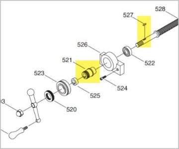
Here is a markup of your system:

The screw shoulder that bears on the bearing inner race from the inside of the saddle is marked A. This shoulder is pulled toward the bearing by tightening the handle nut 303. The force of the nut is transmitted through the handle 302 and parts 525 and 521 which push against the outside of the outer race of the bearing. 521 525 and the handle should all be keyed so they slide on the screw shaft allowing the handle nut 303 to pull the screw shaft tight by pushing on the outside or inside of the bearing. I can't tell which from the drawing.
Your mill uses a different method of capturing the bearing. Your bracket 526 appears to do that. So it may well be that your sleeve system is an inner to inner race system which would mean you can't adjust bearing play out of the system. No big deal though cuz that will be waaaay less backlash than the leade screw nut contributes.
So....... Try removing the handle nut, cleaning the threads, and then tightening the handle nut while you have your 300 thou gap showing. It will probably make it go away as you tighten it.
If not, your bearing may be shot or the sleeve worn down, or the bearing retension system loose, (the two screw collar 526).
That's as much as I can add from SW Ontario. I am absolutely confident that @John Conroy can fix you up lickity split if that wasn't enough info or was incorrect.
Thanks very much for this additional input. Also very clear - apart from me not knowing exactly what all the terms mean. See my expended reply below... Cheers, BrianI'm gunna bookmark this as a first for me. Usually I blather on about nothing and I don't even understand what I wrote myself..... I tend to both write too much and too little. So thanks for that.
In some ways, the Y-axis is easier to work with because the screw is usually short enough to just hang off the table nut in free air and the entire anchor system is built into the front assembly. On a Bridgeport, the leade screw has a shoulder that bears against a bearing the bearing is held in place by a series of sleeves and a round clamp block that looks more complicated than they are. These sleeves do not provide the anchor. They are collectively designed to provide a way to have a floating adjustable index mark so the user knows how much to turn to get how many thou. It has to be loose enough to adjust and also have a way of fixing it so it doesn't move. That makes it look like it's part of the anchor system but it isn't.
The sleeve that has been highlighted in earlier diacussions serves as a transmission of clamping from the handle nut to the outer race of the bearing.
The anchor is actually the nut that holds the handle on in combination with the shaft bearing. The handle nut pulls the system together by pulling the screw shaft toward the user while pushing the sleeve which pushes on the outer race of the bearing. Thus the screw is held to one side of the bearing at the inner race by a shoulder on the leade screw, while being pulled by a sleeve system that bears against the outer race on the other side of the bearing. This should all be tight with the only play being in the bearing itself - which should be minimal because the balls are captured by the opposing forces on the two races.
Mind you, that is how it works on my Bridgeport style saddle. I can't vouch for yours, but it looks similar in many ways but has a differences too.
Here is a markup of your system:
View attachment 52408
The screw shoulder that bears on the bearing inner race from the inside of the saddle is marked A. This shoulder is pulled toward the bearing by tightening the handle nut 303. The force of the nut is transmitted through the handle 302 and parts 525 and 521 which push against the outside of the outer race of the bearing. 521 525 and the handle should all be keyed so they slide on the screw shaft allowing the handle nut 303 to pull the screw shaft tight by pushing on the outside or inside of the bearing. I can't tell which from the drawing.
Your mill uses a different method of capturing the bearing. Your bracket 526 appears to do that. So it may well be that your sleeve system is an inner to inner race system which would mean you can't adjust bearing play out of the system. No big deal though cuz that will be waaaay less backlash than the leade screw nut contributes.
So....... Try removing the handle nut, cleaning the threads, and then tightening the handle nut while you have your 300 thou gap showing. It will probably make it go away as you tighten it.
If not, your bearing may be shot or the sleeve worn down, or the bearing retension system loose, (the two screw collar 526).
That's as much as I can add from SW Ontario. I am absolutely confident that @John Conroy can fix you up lickity split if that wasn't enough info or was incorrect.
Well - that was an enlightening experience. Bottom line - I got the .300" problem greatly reduced. I still have a bit of backlash - about what I was used to before this problem started happening.
With some fear and trembling I started removing parts to get at the mechanism, and that went well - there's only a few parts to remove. I went looking for some sort of fancy adjustment gizmo to tighten things up, but could not see anything like that. I noticed however that the threaded part itself seemed to be way too much toward the front, and I looked for some fancy way to relocate that backwards so as to close the gap. Again - could not see anything, but i then wondered if it might just slide backwards. Well - a push with a finger got me nowhere, but I wondered if I might encourage it a bit with a hammer and small piece of wood? SUCCESS! The hammer moved the whole threaded rod assembly away from me as I sat in front of the milling machine. It seems I was expecting some fancy and clever way of holding things together. The simple truth appears to be that this whole assembly is held "tight" against the casting simply with the nut that also holds the crank in place. Nothing simpler!
I now think what happened is that this nut came loose while I was using the machine and gradually the gap widened. Maybe a small drop of Loktite before I call this job done? Do not want to overdo things and hold that nut forever in place, but it surely will come loose again.
BTW - I now realize that a complete disassembly is really not needed for this adjustment. I think that just tightening the nut - as Susquatch mentions - will be all that is needed. The gap is now about what I remember from the early days using this machine. Still not as tight as the X axis, but way more usable than before. So thanks everyone for helping me have the confidence to fix this issue. Some things in this world are a lot simpler than they first appear I have now found out.
Now on to the other two issues - installing the DRO gear and replacing the motor. Can I remind Edmontonians that I am very happy to pay for help with either or both of these tasks. Heck - it might even be that someone from elsewhere is coming to Edmonton and needs something to keep him or her busy! All help gratefully received.
Many, many thanks to those who took their time to help out. Also those who might have been cheering from the sidelines!
SUCCESS! The hammer moved the whole threaded rod assembly away from me as I sat in front of the milling machine.
Well, to be honest with you, I'm not as happy as you are.... I think you are only putting a bandage on it.
Using a hammer on the screw simply pushes that collar that I marked as "A" away from the rear of the bearing. Yes, that will take up the play. But it will come back as the collar moves back to the bearing.
If the handle nut won't remove it when it does, cuz there isn't enough thread there, try adding another sleeve (think thick washer) between the handle and the nut or between the indicator sleeve and the bearing or someplace in there. They should not wear because the shaft is keyed and therefore everything turns as an assembly.
I suppose it's also possible that the bearing is shot or you pushed the bearing back in its seat where it belongs. In this case, you either need a new bearing or the bearing holder came loose, or the bearing holder will need a sleeve to keep the bearing where it belongs.
The only other obvious explanation in my mind is that the collar A is sliding on the shaft. But since it doesn't have a part number, it is probably a machined feature. In which case you are back to a bad bearing or a loose nut that won't fully tighten anymore.
In any event, pushing the screw back is a temporary fix if you can't also take up the resulting play some other way.
Edit - See! There I go again yammering on without sufficient explanation to make my comments meaningful. Feel free to ask if anything isn't clear. I promise I won't take offense. I know I'm often hard to follow.
Why don't you try and look at that collar A next time you get the chance. Also look at the bearing retainer to make sure it's adequately securing the bearing, and make sure the bearing is good. That should all be an easy disassembly.
Thanks for the further input. I am nowhere an expert on machinery and the field of engineering is far from my mind. But - that nut that holds the handle on would seem to me a simple, yet adequate way to keep things from getting further apart. It was you who suggested that tightening the nut would have the desired effect, right? When it comes to using a hammer - I did try with a finger, but that would not work. So I did use a small hammer and a piece of wood, and that moved things into position. At no time did the hammer strike the metal - so I did avoid any damage that might cause. I am hoping this stays working for a while at least. Do you have an opinion about a drop of Loktite on the nut to keep it in place?Well, to be honest with you, I'm not as happy as you are.... I think you are only putting a bandage on it.
Using a hammer on the screw simply pushes that collar that I marked as "A" away from the rear of the bearing. Yes, that will take up the play. But it will come back as the collar moves back to the bearing.
If the handle nut won't remove it when it does, cuz there isn't enough thread there, try adding another sleeve (think thick washer) between the handle and the nut or between the indicator sleeve and the bearing or someplace in there. They should not wear because the shaft is keyed and therefore everything turns as an assembly.
I suppose it's also possible that the bearing is shot or you pushed the bearing back in its seat where it belongs. In this case, you either need a new bearing or the bearing holder came loose, or the bearing holder will need a sleeve to keep the bearing where it belongs.
The only other obvious explanation in my mind is that the collar A is sliding on the shaft. But since it doesn't have a part number, it is probably a machined feature. In which case you are back to a bad bearing or a loose nut that won't fully tighten anymore.
In any event, pushing the screw back is a temporary fix if you can't also take up the resulting play some other way.
Edit - See! There I go again yammering on without sufficient explanation to make my comments meaningful. Feel free to ask if anything isn't clear. I promise I won't take offense. I know I'm often hard to follow.
Do you have an opinion about a drop of Loktite on the nut to keep it in place?
Yes, It was me that had suggested tightening the nut. But that should have worked without the hammer. Needing a hammer means you had to push the screw back, whereas tightening the nut means pulling the screw forward. They have somewhat opposite affect on the leade screw's axial position.
No, I wouldn't loctite the handle nut. You can if you want, and doing so won't hurt anything. But I think a periodic retightening is better practice. I took mine apart just now to look for other explanations. Mine was locked up pretty solid and has no loctite on it. The shaft key should stop things from turning loose.
To me, it makes more sense to focus on finding out where the play is. It's someplace between collar A and the handle nut. There are only a few spots in there to check.
You did the right thing pushing the screw with a block of wood between the thread and your hammer. But pushing the screw back isn't going to provide a permanent fix. The collar A needs to be pulled toward you up against the bearing not pushed away from it. Pushing the screw shaft back does remove the play, but it will come back..
Assuming Collar A isn't loose or damaged, it actually needs to be pulled toward you not pushed back. This will probably create the gap that you don't want, but the gap is what you need to address with the Collar A all the way toward you, not pushed back.
If you want, send me a PM with your phone number and availability and I'll call you so we can talk. And have your drawing handy. That allows for the instant feedback we don't get in posting back and forth like this.
I like your approach to this. But let me say this... I certainly agree that tightening the nut would have solved the problem. It is just that I had the parts disassembled when I took the hammer and wood to see if I could move the leadscrew backwards - away from me if you like. And that worked - leaving a lot more threads for the nut to turn onto when I put it all back together. With the nut newly tightened using all the threads - the gap is almost gone - certainly I can live with the situation as it now is. Providing the nut stays tight - and I agree I can tighten it from time to time - all should be well. Apologies if I do not explain things perfectly - but things get a little confused to this old accountant. Not helped a lot by the fact that this leadscrew is left-threaded and if you turn it clockwise - if comes toward you as you sit in front. Probably makes a lot of sense to an engineer, but seems a little odd to me. I will look into getting you my telephone number by PM - if I can figure out how to get that information. Cheers, BrianYes, It was me that had suggested tightening the nut. But that should have worked without the hammer. Needing a hammer means you had to push the screw back, whereas tightening the nut means pulling the screw forward. They have somewhat opposite affect on the leade screw's axial position.
No, I wouldn't loctite the handle nut. You can if you want, and doing so won't hurt anything. But I think a periodic retightening is better practice. I took mine apart just now to look for other explanations. Mine was locked up pretty solid and has no loctite on it. The shaft key should stop things from turning loose.
To me, it makes more sense to focus on finding out where the play is. It's someplace between collar A and the handle nut. There are only a few spots in there to check.
You did the right thing pushing the screw with a block of wood between the thread and your hammer. But pushing the screw back isn't going to provide a permanent fix. The collar A needs to be pulled toward you up against the bearing not pushed away from it. Pushing the screw shaft back does remove the play, but it will come back..
Assuming Collar A isn't loose or damaged, it actually needs to be pulled toward you not pushed back. This will probably create the gap that you don't want, but the gap is what you need to address with the Collar A all the way toward you, not pushed back.
If you want, send me a PM with your phone number and availability and I'll call you so we can talk. And have your drawing handy. That allows for the instant feedback we don't get in posting back and forth like this.
It is just that I had the parts disassembled when I took the hammer and wood to see if I could move the leadscrew backwards - away from me if you like. And that worked - leaving a lot more threads for the nut to turn onto when I put it all back together.
If nothing else, you are definitely a huge source of mysteries!
I would have thought that pushing the leadscrew in like that would have left fewer threads, certainly not more!
Are you sure that you didn't push the collar stack in instead of the leadscrew? Cuz that would leave more threads and definitely explain the end result - which in that case would prolly be a lasting solution!
I remember at the beginning when you said this would all turn out to be simple. I have a saying for that and it goes like this:
"This problem too will be simple when solved!"
It is just that I had the parts disassembled when I took the hammer and wood to see if I could move the leadscrew backwards - away from me if you like. And that worked - leaving a lot more threads for the nut to turn onto when I put it all back together.
Now I'm confused😕 How did pushing the leadscrew away expose more threads for the handle nut?
@Susquatch and I posted at the same time....
Last edited:
A really big OOPS... Susquatch and Craig have been confused because I apparently said the wrong thing - or the right thing backwards... Anyhow - sorry for my lack of precision. I did not hammer on the leadscrew in making my repair. I actually hammered on what Susquatch is calling the collar stack. Or in the parts list it is part number 521 I believe. Anyhow - by hammering that away from me it exposed more of the threads and so the nut went on further, taking up the huge gap that was there yesterday. I think that's correct now. And I think that from now on, a simple tightening of the nut holding on the handle will keep things decently tight and operating well. Once more - a sincere thanks to those who helped with this. Much appreciated. Cheers, Brian
I think that's correct now. And I think that from now on, a simple tightening of the nut holding on the handle will keep things decently tight and operating well.
Spot on Brian. All is well in my foggy confused world with that clarification.
You should be good to go for a long while now. Maybe tighten that nut every once in a while just in case as well as take up any slack that results from the stack settling in with use.
Eventually, you might have to take it all apart and find out how the gap came to be. Given you are a few years older than me, that might never happen. Which is perfectly ok too!
If I understand, you discovered the 521 part was to far forward towards the handle & you were able to shift it back in the leadscrew direction? If so, maybe sticky keyway or sticky ID/OD, but anyways sounds like its landed where it should be & made up the bulk of 0.300" gap?I actually hammered on what Susquatch is calling the collar stack. Or in the parts list it is part number 521 I believe. Anyhow - by hammering that away from me it exposed more of the threads and so the nut went on further, taking up the huge gap that was there yesterday.
Now that its been disassembled & you have seen the internals:
- is the 520 part like a knurled threaded ring? @Susquatch is suggesting that is (typically at least) a tightening ring in order to set the graduation dial. So you loosen it, rotate the dial to some desired graduation mark & then tighten again which is how it should reside. Is that how you have been using & it is normally hand tight?
- so the acorn nut on very left of exploded view, does that thread onto the threads of the shaft & retain the handle? (The handle bore has no keyway?). That's the part I'm still confused about. What does the rear face of handle bear upon because the sketch shows the next part is 520 part?
Attachments
Peter That is correct. I shifted the [art 521 away from me as I face the machine, and that was done with a hammer and small piece of wood. It seems I did not have to use this approach - I could have just tightened the but instead - same effect...If I understand, you discovered the 521 part was to far forward towards the handle & you were able to shift it back in the leadscrew direction? If so, maybe sticky keyway or sticky ID/OD, but anyways sounds like its landed where it should be & made up the bulk of 0.300" gap?
Now that its been disassembled & you have seen the internals:
- is the 520 part like a knurled threaded ring? @Susquatch is suggesting that is (typically at least) a tightening ring in order to set the graduation dial. So you loosen it, rotate the dial to some desired graduation mark & then tighten again which is how it should reside. Is that how you have been using & it is normally hand tight?
- so the acorn nut on very left of exploded view, does that thread onto the threads of the shaft & retain the handle? (The handle bore has no keyway?). That's the part I'm still confused about. What does the rear face of handle bear upon because the sketch shows the next part is 520 part?
The 520 part is exactly like you describe. I threads onto the largish threads on part 521 and clamps the dial firmly enough that it rotates as you turn the handle - or crank if that's a better term. That is how I originally used it and will again now that I do not have to turn it 2.5 times to reverse direction!
The nut threads onto the threaded part at the end of part 527. It does retain the handle but most importantly, it also brings forward part no. 527 so the gap is minimized. If the nut is tight on hart 527, it cannot go forward or backward - apart from a little "slack" which might be unavoidable in the machine. I might try and make a washer to see if I can reduce the gap even more - but it is working quite well for now. Actually the handle bore does have a keyway and mates with the key in part 527. So, the handle turns exactly with part 527. Looks like about a 3mm key. The back side of the handle rubs against part 520 and turns part 527 and the dial as well of course. When changing directions there is a very narrow gap between the back of the handle and part 520 - maybe .01" now. This was .300" before so a considerable improvement - as long as I keep the nut tightened.
I hope that answers all your questions. If I have been unclear, please keep asking.