• Scam Alert. Members are reminded to NOT send money to buy anything. Don't buy things remote and have it shipped - go get it yourself, pay in person, and take your equipment with you. Scammers have burned people on this forum. Urgency, secrecy, excuses, selling for friend, newish members, FUD, are RED FLAGS. A video conference call is not adequate assurance. Face to face interactions are required. Please report suspicions to the forum admins. Stay Safe - anyone can get scammed.
  • The 2026 Calgary Area Meetup is set for Saturday May 30th at 10am. The signup thread is here! Robinhood has graciously offered to host the meetup again this year. Please note that you MUST RSVP to the notice linked above if you wish to come.

Help - I'm confused (about file formats and workflow)

someidiot

Well-Known Dismemberer
Okay, so I get the idea behind the .STL file for describing solid objects, and that's the format that the "test rook" model supplied by Elegoo comes in - the printer reads the file and spits out the object (Imagine taking the printer, a bottle of resin, and a 12V solar panel back 200 years - "Any sufficiently advanced technology is indistinguishable from magic"). And I get that there's "slicer" software that takes the 3D model and splits it into the layers appropriate for printing.

But what I don't get is how these pieces fit together. How can the .STL file describe both an object and the slices you wish to render it as - unless each layer is represented as a separate object in the file and they're simply printed in order? So does that mean there are two versions of .STL files - unsliced and sliced - and that the slicing software turns the former into the latter?

I'm led to the question because as soon as I got this thing running, my daughter expressed interest in wanting to print a bunch of small frobs (details unimportant) for which there are ample free models available - but apparently for filament printers (rather than resin), which implies that the model would have to be resliced (i.e. resampled) for the thinner slices the latter renders. Or do I really misunderstand this?
 
But what I don't get is how these pieces fit together. How can the .STL file describe both an object and the slices you wish to render it as - unless each layer is represented as a separate object in the file and they're simply printed in order? So does that mean there are two versions of .STL files - unsliced and sliced - and that the slicing software turns the former into the latter?
This may or may not help but FWIW, AI says this...

There are not two versions of STL files. An STL always contains only the 3D surface geometry (a mesh of triangles) — it never stores slices or layers. The slicing step does not produce a "sliced STL"; it produces a G-code file, which is a completely different format containing the actual machine instructions (nozzle paths, temperatures, speeds) for each layer.

Here's how the pieces fit:

  1. STL = a closed triangular mesh approximating the object's outer surface. That's it — no layers, no toolpaths, no units, no material info.
  2. Slicer (Cura, PrusaSlicer, etc.) takes that mesh and mathematically intersects it with horizontal planes at regular Z-intervals (the "layer height"). The resulting 2D cross-sections are computed on the fly and never written back into an STL.
  3. G-code = the output. It encodes the XY toolpath for each layer, plus all the machine-specific settings (speed, temperature, flow rate). This is what the printer actually reads.
So the mental model is: one STL in → slicer computes layers in memory → one G-code file out. The "slices" exist only as intermediate calculations inside the slicer; they are not a second kind of STL file.
 
Okay, I've got all that. And (without looking it up) I'll take a SWAG that G-code is some kind of "enhanced" (i.e. bastardized) version of the Gerber standard that we all know and love from PCB manufacture.

But that doesn't answer how the Elegoo printed the sample rook model, which came in a zip containing exactly two files - Rook.stl and _Rook.ctb - unless, when I selected the .stl, it actually printed from the .ctb that was also in the same directory. Wait - no - that doesn't make sense either, because Gerbers are ASCII and both of these files are binaries. So I remain confused.
 
But that doesn't answer how the Elegoo printed the sample rook model, which came in a zip containing exactly two files - Rook.stl and _Rook.ctb

The 3D printing noob would like to take a shot at answering that. A test of my growing understanding if you will.

Once you have a 3D model (STL file), nothing says your printer can't have a built in slicer. To the user, it looks like the printer prints STLs, to the printer, it's just some built in software.

I'll take a SWAG that G-code is some kind of "enhanced" (i.e. bastardized) version of the Gerber standard

G-Code is just a set of move and execute instructions typical of CNC machines. Go in the X Direction x amount, turn on nozzle or cutter, go in y direction y amount, etc etc.

Happy to be criticized. Hopefully didn't confuse the issues for anyone.
 
So the mental model is: one STL in → slicer computes layers in memory → one G-code file out. The "slices" exist only as intermediate calculations inside the slicer; they are not a second kind of STL file.

Correct, STL is a defined file type, basically mesh of facets. It can vary by mesh size/density but its fundamentally the same. Its actually an old format. Some slicers (Bambu I know but probably others) can accept more modern input files STEP for example. If it can, its a better way to go.

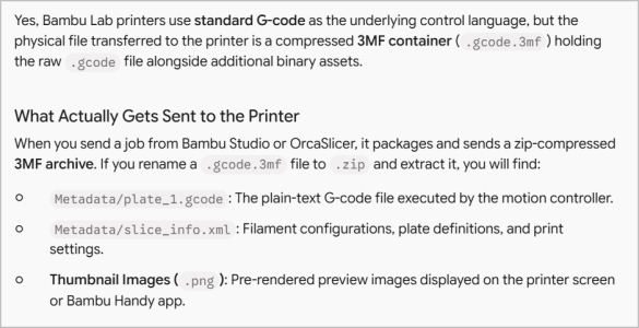
Q2) Not my field of expertise but I think depends on hardware. I think most lets call them 2.5D 3DP filament slicers output G-code for the physical nozzle movement. But there are other goodies in the output file that the the printer sees pertaining to hardware & print specific parameters (speeds, calibration, maybe filament change..). So Resin printers would be very different in this regard even though its using the same STL or whatever to define the shape. Here is a Bambu filament 3DP filament explanation hinting at whats contained in their wrapper file.

1790705815124.png
 
Once you have a 3D model (STL file), nothing says your printer can't have a built in slicer. To the user, it looks like the printer prints STLs, to the printer, it's just some built in software.

That's what I was thinking too - cut out the middleman. But that fails to explain why Elegoo supplies and/or recommends slicers for use with their resin printers. The immediate problem I need to solve is the model-stuck-to-platform, which (obviously) means reducing the exposure time of the first layer(s) printed. The Mars2P doesn't have any provision (i.e. front panel) for changing that kind of parameter, so some file's gotta be opened in something that does, and it doesn't make a lot of sense to me that it's the kind of information that should be stuffed into an STL file along with the geometry.
 
Correct, STL is a defined file type, basically mesh of facets. It can vary by mesh size/density but its fundamentally the same. Its actually an old format. Some slicers (Bambu I know but probably others) can accept more modern input files STEP for example. If it can, its a better way to go.

Right - it actually comes from the granddaddy of resin printers, stereolithography inventors 3D Systems:


I learned about those guys way back in 1990 or so when their machines cost on the order of $250K (and up, iIrc). I was under the impression that the Manitoba Research Council had one at the time. Then consumer filament-3D-printing happened and I had no idea what had happened to the original stereolithography market until learning recently (thanks to the very unflattering documentary on Makerbot) that 3D Systems is not only still around, but the big dog, and that consumer resin printers (e.g. Elegoo) had appeared.
 
The STL is (as mentioned above) just the geometry. No machine settings or toolpaths. A 3D printer can't use this directly without a slicer. Theoretically, they could integrate a slicer into the printer itself that's "seamless" but I don't think anyone has done this yet.

The CTB is the "sliced" file for your SLA printer with all the appropriate machine settings and cross sections for every layer. It is not a g-code file because it stores different information differently, much like how videos aren't stored in .jpeg format. It is a binary file format.

Gcode is used on FDM 3D printers, machine tools, some robots, etc. It's basically just a list of "go to this position at this speed" plus other machine specific commands, many of them standardized, many not depending on the industry. It's an ASCII file format.

.3mf and others are used to re-package gcode with other files. .bgcode also exists as a binary version of traditional g-code to make files smaller and faster (and to make this all more fun and confusing).
when I selected the .stl, it actually printed from the .ctb that was also in the same directory.
I'm pretty sure this is what happened.
 
That makes a reasonable amount of sense. I just have to pay closer attention to the files themselves e.g. if I change the printing parametrics (using "whatever", in this case Chitubox), which files are modified - suppose I could even (binary) diff them to "prove" that something was changed, and where. But that makes the printer's UI a little weird, because I'm sure I selected the STL for printing, which would mean it pulled a bit of a sneaky by actually printing from the CTB. I can alway futz around with deleting the latter just to see if/how it errors when I try to print the STL (unless I'm truly out to lunch re: which file I chose for printing).

It would make a ton of sense, of course, for this resin printer - which uses a big UV LED array display to cook the resin - to use an input file other than G-code. As I said, I'm assuming that G-code was derived from the old Gerber format, which in the days of 3D systems' putting a laser over the tank (above a platform that lowered as the model was built) would still have made sense. But with an array like the Elegoo uses, having that path information as input would be a nuisance - you'd have to follow/interpolate/whatever the whole layer's path in order to then expose it at once, rather than as a "moving point tool draw". So that's probably the origin of the CTB (will have to look further into that).
 
Last edited:
Back
Top