• Scam Alert. Members are reminded to NOT send money to buy anything. Don't buy things remote and have it shipped - go get it yourself, pay in person, and take your equipment with you. Scammers have burned people on this forum. Urgency, secrecy, excuses, selling for friend, newish members, FUD, are RED FLAGS. A video conference call is not adequate assurance. Face to face interactions are required. Please report suspicions to the forum admins. Stay Safe - anyone can get scammed.

Tool Help 300lb table crane - must be some mechanical engineers around here?

Tool
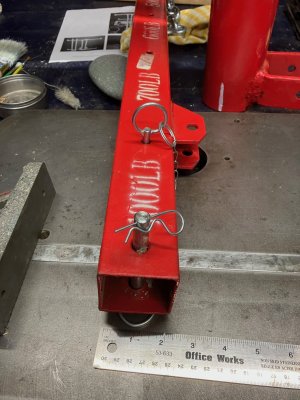
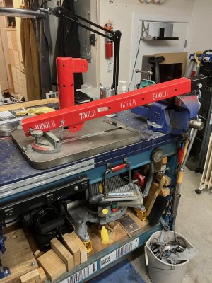
My PA 1000lb mini truck crane easily moves my 500lb lathe. Bolted to my work bench. Two pieces of angle iron beneath the bench bolt to the crane mounting plate on the bench top, six 1/2" bolts connect the top and bottom.

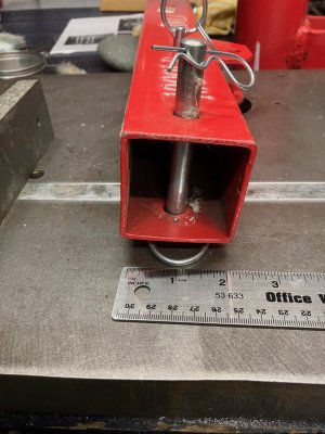
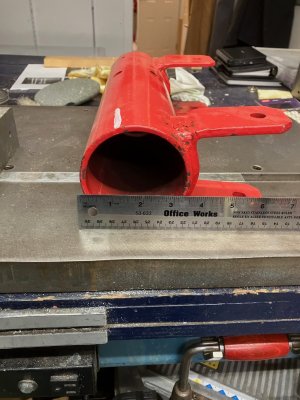
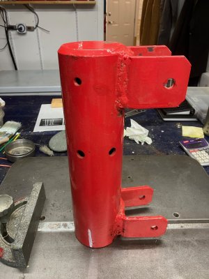
The horizontal beam is 2x2x3/16 steel HSS, the vertical rotating cap is 3" Sch40 pipe.

what size is your vertical post?

IMG_2134.jpeg
 

Attachments

  • IMG_3514.jpeg
    IMG_3514.jpeg
    455.3 KB · Views: 7
  • IMG_3513.jpeg
    IMG_3513.jpeg
    438.6 KB · Views: 8
  • IMG_3512.jpeg
    IMG_3512.jpeg
    488.7 KB · Views: 8
  • IMG_3511.jpeg
    IMG_3511.jpeg
    410.5 KB · Views: 8
  • IMG_3510.jpeg
    IMG_3510.jpeg
    404 KB · Views: 7
What i was getting at was dont over think it, it doesnt take much to support 300lbs even at 4ft

a 2x2 or 2x3 with a gusset/small knee brace or maybe a strut on top in tension to reduce any deflection

if i were to do it with a telepost, as was noted, (given there are many sizes of of teleposts, and assuming a round post) i would probabaly think of finding a collar that would slide over the outside of the telepost, maybe a foot long, tube welded to the top, knee brace or gusset welded to the bottom of the collar or tube on the bottom and tension strut to the top. then a guy could make use of the already drilled holes for rough height adjustment, crank the telepost to the roof, nail the top, secure at the bottom (anchors, or welded to a heavy bench)
 
if i were to do it with a telepost, as was noted, (given there are many sizes of of teleposts, and assuming a round post) i would probabaly think of finding a collar that would slide over the outside of the telepost, maybe a foot long, tube welded to the top, knee brace or gusset welded to the bottom of the collar or tube on the bottom and tension strut to the top.

Now that we can agree on.
 
Amongst other things, I am an engineer, so perhaps I can help. Before getting into the details, consider the basics.

A 300 pound load at the end of a 4 foot beam will produce reaction forces like in this diagram. That means that the joint at the top of the post needs to withstand 1200 foot pounds of torque (moment). Assuming it is 3" square stock, that requires 4,800 pounds of tension resistance on the top, and the same in compression on the bottom. Connection details matter a lot, but it is hard to see a way to achieve this level of resistance at these dimensions (yield strength of structure steal assumed to be ~300 MPa and good welds are about 1/3 of that). Adding gusset plates will help, but how big to they need to be? With this design I expect 18 - 24 inches with double plates. But it depends a lot on what the post is made of because with real materials the true forces depend more on strain compatibility than pure elastic theory - i.e. everything bends to some degree

As others have mentioned, the key to the strength of the commercial product is that it is a cantilever design. That means that the beam part sticks out the back some distance. And there is a connection from the back of the beam down to the post. This helps in two ways. First, the increased distance generates torque with less force. Second, this applies stress to a part of the post that is 'far' from the critical region. This allows a thinner section to be used overall.

The second picture shows a geometry that is much more efficient. for the beam portion, use 1/3 and 2/3 portions and tie it back at 45 degrees.

I hope this helps

1699313264188.webp
1699314762730.webp
 
Me too. that's what is causing me to build a bridge crane.

The motivation for the rotating design concept that I originally sketched was that it would rotate out of the way when not in use (99.9% of the time). Unfortunately there is no room behind the mast for a pivot arrangement because the post will be very close to a wall. So either I build it as proposed with a larger gusset and a lower rating say 100lbs, or the bridge crane concept could work I would just have to remove the bridge portion when not in use. A 6' bridge could run from where I was planning to place the tele-post diagonally across the work bench to a tool chest that sits next to the work bench. Would need some sort of miniature I-Beam or C-Channel to incorporate a sliding drop.
 
I have 2 in my garage and I am adding 3rd. Based on the top part of PA 2t crane. Single clamp at the top & rotating. I managed to lift max of 1t with one of them. I can take pictures.
 
It is hard to tell exactly from these pictures, but there are a couple of key features. First the through plate and wrap around weld looks like it about triples the weld length. But more importantly, it adds weld on both the front and back of the socket. That allows the joint to develop strength over distance - even a small distance makes a huge difference. It also puts the welds in shear instead of direct tension which makes a sudden failure much less likely - what Susquatch called 'zippering' can't happen because the bead of weld metal has to be pushed through the other metal which is stonger.

This configuration also allows the arm to be tilted. It can support more weight at a higher angle.

I'm not sure what a bridge crane is, but I am almost sure that something you will buy will be cheaper than something you will make
 
In the past he made out like he knew a lot more than he actually did, and made a fair number of significant errors in his overconfidence. Way too many to remember, but for instance a 17 degree relief taper on a shaper tool. And then complaining that the tool didn't last long. So it was the cobalt HSS fault. sheesh.
 
I also stopped watching his videos. Like CEE videos, kind of cringe though when he puts a length of pipe on the chuck wrench to tighten the jaws on a part.
 
I'm glad someone mentioned the bending moments at various joints.

Don't forget the highest load is at the base for tipping, enforcing the post base is easy, what most forget is the fasteners and floor to hold it down. This where your biggest risk of ultimate failure (and most dangerous failure) is going to be.

A regular concrete slab is not enough depending on the load.
 
length of pipe on the chuck wrench to tighten the jaws on a part
CEE uses that on his 16" chuck. That means for that 5inch-ish range of tubes and barstock he is clamping on, all or all but one of the teeth engage the scroll. These jaws are almost 2" thick, so say, 2" X 11 teeth X 3 jaws, with a .100 advance on 1 turn (these measures are approximate from the vids). Thus he has about a 25:1 advantage, so 200 ft lbs results in 5000 lbs of force available. Worm gears are about 70% efficient, so that leaves 3500 lbs of force distributed over 33 teeth/scroll section. About a third of each tooth will be holding the majority of the force, so, say 66 inches / 3 or 22 inches, or about 160 lbs per tooth. at 1/8 inch depth of scroll this isn't damaging in any way.

It looks scary and bad, but it is fine. I was freaked out when I first saw it, but I ran the numbers, so I'm not worried. :cool:

However, using a cheater on a small chuck with 5 teeth engaged over a 1 inch jaw this force would wreck the scroll or the teeth on the jaws. :mad:

Well said @Dabbler. I see WAAAY too many folks using cheater.bars on chucks far too small to take it.

Perhaps worse than the jaws is the camlocks on the spindle.
 
Back
Top