• Scam Alert. Members are reminded to NOT send money to buy anything. Don't buy things remote and have it shipped - go get it yourself, pay in person, and take your equipment with you. Scammers have burned people on this forum. Urgency, secrecy, excuses, selling for friend, newish members, FUD, are RED FLAGS. A video conference call is not adequate assurance. Face to face interactions are required. Please report suspicions to the forum admins. Stay Safe - anyone can get scammed.

Tool Help 300lb table crane - must be some mechanical engineers around here?

Tool

slow-poke

Ultra Member
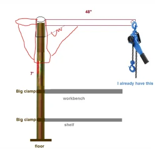
Being the ever thrifty but suddenly in need of a mini workbench crane kind of guy, I conjured up the following image of the ~$100 DIY version of the TelePro.

I already have a lever chain lift, so just need to get two pipes for the mast (7' and 1'), the lateral beam and two clamps.

Question is:
0) Is this a really bad idea? assuming not.....
1) How small can I go with the mast; diameter and wall thickness? Found a telepost on marketplace, I think that should be adequate?
2) For the lateral beam, round or some sort of mini I-Beam?, and suitable (minimal) size? I suppose I could get two teleposts and use one for the lateral beam?


I can weld.

mini-crane-R1.webp
 
Last edited:
I would guess its a very bad idea. I think the Tele Pro design transfers the downward forces of the load to be directly over the vertical supporting post whereas your design leaves all the downward force of the load at the end of the horizontal member. Therefore in your design there would be huge stresses on the joint between the vertical post and the horizontal member. I'm just a physicist tho not an engineer.
 
Ya, not a good idea - at least not in comparison to the model you aimed at. Although they look similar in some respects, they are actually very different.

I prefer not to get involved in the design of lifting devices because of the safety and liability implications of doing so. But I have no qualms about recommending against your design......

That's not to say it would not meet your needs. But it's not going to perform as well as you might want and certainly not as well as the one you used as a benchmark.

I assume you think an engine lift takes up too much room. But you could always shorten the boom and legs to work. As long as the legs reach further than the shortened boom can reach they can be very strong. In fact, much stronger than even your benchmark.

Why not use a hydraulic or scissor lifting platform?

Or maybe a small two post gantry design that rolls over and straddles the workbench. There are lots of proven designs around that should meet your needs.

I confess that I am quickly reaching the point where I might need to do something similar. I did a recent project (grinding wheel balancing rings) that required me to move my 10" Rotary Table to my mill table and then back off again when I was done. I'm a big strong fellow - especially for my age. But man that thing felt heavier than I expected...... I'm sure glad the distance wasn't great......
 
Last edited:
I confess that I am quickly reaching the point where I might need to do something similar.
Me too. that's what is causing me to build a bridge crane.

0) Is this a really bad idea? assuming not.....
@slow-poke the design of your adaptation isn't nearly as strong as the commercial one, not matter how good your welds are. Calculation forces can be very surprising when you get into the analysis.

Before I go off prematurely, I'll deep dive tele pro cranes and see what makes them special. Do you have a specific lifting range, max load, reach, etc? That really is the place to start.
 
Obviously at 1/60 of the cost it's not going to be as strong or user friendly, certainly wasn't implying that.

Agreed regarding the weight transfer, however the one in the image is rated 2500lbs and extends to 82", so the forces are not comparable.

If welded properly it's not obvious to me how the cheapo version would fail?, my hunch is that the most likely failure would be folding of the lateral beam at the edge of the gusset.

Existing shop crane can't roll under the bench.
 
Last edited:
Me too. that's what is causing me to build a bridge crane.

Before I go off prematurely, I'll deep dive tele pro cranes and see what makes them special. Do you have a specific lifting range, max load, reach, etc? That really is the place to start.
300 lbs max, 48"

My shop area is quite small, bench is against a wall and no room for bridge arrangement.
 
Last edited:
For what it’s worth, I have something similar I copied from work.
If it’s good enough for the Gvt of Canada it’s probably good enough for me.
Design came from good ole PA years ago. They no longer sell it.
I’ll try and post pics and measurements later. Vertical tube is probably 1/4” wall maybe 3” tube.
it lifted 7.5 hp 2 stage 80 gallon compressor no issues.
Home shop engineering, when in doubt use R&D ( rip off and duplicate)
Sounds promising, can't wait to see.
 
Between the two designs shown: the Tele is designed using a cantilever, similar to construction cranes, the reaction to the lifted weight is directed straight down into the round column. The column would essentially need to crush for this to fail. Your design is a simple lever with the column edge as the fulcrum, even with a gusset, this is a weak design. A 48" lever with 300lbs would exert over 7000lbs of on the column which would likely cause it to buckle just under the gusset. Think of a drinking straw, they are pretty strong if try to crush it but will buckle easily with any side load.
 
The original design, the tension in the turnbuckle on the left is being used to cancel to moment force generated by the weight at the end of the boom. Your proposed design, without this element, will want to twist itself apart. You are relying on your welds to hold everything together, they have engineered it so that the forces are balanced and all of the force is straight into the column.
 
I think a good way to describe the weakness in your concept is to imagine the difference between trying to pull two welded parts apart in a linear direction and conversely twisting one against the other. The smaller the twisted area, the greater the force multiplication. You have two very long beams connected at a very small hinge point. The leverage will try to twist the weld apart which is easy to do. You are better off with welds that are pushed together or pulled apart. Welds lose their strength rapidly when they are zippered with a short plus/minus moment load that is both greater at the ends than at the center and also multiplied by the leverage of the length of the two arms.

It is MUCH BETTER to put a hinge pin in there to let it flex as much as it wants and then use a long strut to resist/hold the moment induced by the load. Don't underestimate how important this factor is even with what you might think are just minor loads. The hinge cannot hold torque loads so it simply doesn't, and the strut is just a fixed point that only sees tension and compression.
 
I mounted a PA pickup truck crane to my work table. So far it's worked pretty decent. Bottle jack lift. I think it's rated for 500 lbs?
The front bumper I'm rebuilding for my Toyota is hanging from it as we speak.
 
So here is my 2 cents is to make sure the pipe its thick wall stock, The cap thick also and longer, rib longer, and add on to the back side also... !! ANDDD !! don't put your feet under the lifted part !!
 

Attachments

  • 1699291631477.webp
    1699291631477.webp
    18.6 KB · Views: 5
Last edited:
well not nailed! hopefully welded, and not with jb weld!

I really did like your example cuz the truth is that a wooden 2x4 beam nailed to the top of a wooden post might hold 300 pounds. But the nails at the top of the post will pull out. It's a very similar situation with a steel tube beam and welds. The forces involved sky rocket as the flange or gusset get smaller. With a 3 inch joint, the load at the flange is not 300 pounds, it is 300x4ftx12/3 = 4800 pounds over the 3 inch joint. Now consider that it's a plain bead weld and it's easy to see that the weld could zipper starting at the far end of the weld.

Will it happen? Maybe, maybe not. But why take chances?

The problem is so easily solved with a pin hinge at the post and a strut like all the PA lifts have that @whydontu linked to or by a much wider flange like the one drawn by @Matt-Aburg or by a dozen other ways to avoid focussing the load.

To be clear, I am not against welding. Nor am I opposed to a simple design. Nor am I saying that it will fail. I am simply pointing out that it is a much better design if the beam loads are re-arranged or spread out (preferably both) so the weld cannot zipper starting at the rear of the post. It is such an easy fix and improves the design many times over. It also reduces the chance of the beam buckling. With all that going for it, why wouldn't you do it?

Furthermore, pinning the beam to the post and installing an adjustable strut also makes the design more flexible because the beam can be lifted for more clearance over the bench.

It's stupid simple to do and very strong too.

Now let's talk about the anchors to the bench....... LOL!
 
Back
Top