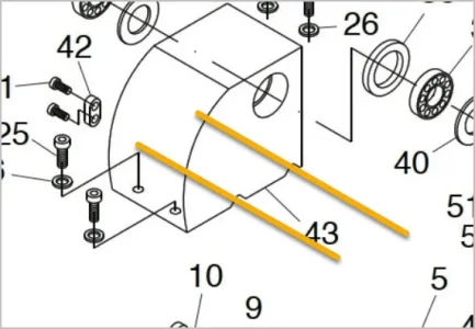
Well, on my 10 hp, 19” swing CMT lathe there are 6 bolts, one pin to swivel about, and an adjusting block at the very left end under the HS holding things in alignment.On a side note, how sufficient would 4 bolts mating two flat surfaces be for a headstock? No V seating or anything else, just two surfaces stuck together with 4 bolts in slightly oversized holes holding it together.
I would think on a lathe your size four bolts, a pin and the adjuster should be strong enough to secure the HS to the bed.
My guess is you are thinking of machining the V off the bed and just bolt the HS to it (properly aligned)?