• Scam Alert. Members are reminded to NOT send money to buy anything. Don't buy things remote and have it shipped - go get it yourself, pay in person, and take your equipment with you. Scammers have burned people on this forum. Urgency, secrecy, excuses, selling for friend, newish members, FUD, are RED FLAGS. A video conference call is not adequate assurance. Face to face interactions are required. Please report suspicions to the forum admins. Stay Safe - anyone can get scammed.

Hardened Steel Jaws for Wood Handling - Can These Be Machined?

CalgaryPT

Ultra Member
Vendor
Premium Member
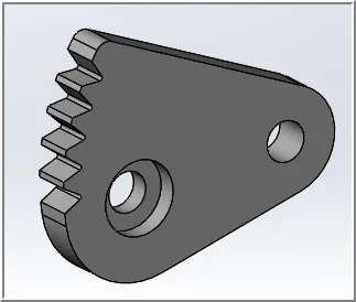
Hi everyone—I'm just fishing around right now, but I may have a big project over the winter building a customized wood handling machine for a friend. One of the components on it is a set of steel jaws, which I think would need to be hardened. I don't have all the details yet...but basically they need to grip dimensional lumber and pull them with 2+ tons of force through another machine. The jaws are cams (more or less) with "teeth" on them. I don't have exact dimensions yet, but am guessing these "cam jaws" are roughly 3/4" to 1" thick steel—maybe 3" by 6" in size for the raw stock before the cam shape is cut.

I am more of a weldor and fabricator than a machinist. Are these cam jaws something one can buy? Is something like this easily machined? Can you then take it somewhere (in Calgary) to be hardened? I think it needs to be kind of similar to a pallet puller in terms of hardness or ruggedness...or maybe similar to the feed roller on a wood chipper ??? (I don't own a wood chipper, but I have seen Fargo if that counts.)

Sorry for the stupidity....but I'm way out of my comfort zone here when it comes to machining and especially hardening steel.

I've attached a pic (I know, the resolution is terrible) that approximates what I think needs to be built. I'll know more in a month or so if my friend wants to proceed. Right now I am just researching if this is even something a machinist could do, or if it is something different...such as casting? If it is a machine shop job, and someone on this forum could do it, I'd love to work with you. Best part is the machine he is building is a one-off prototype for his business, so this is more of a proof of concept than a production run—he isn't shooting for perfection and it will probably be a trial and error project with a few iterations (all of which he would pay for). I'm comfortable with the CNC plasma cutting, welding, and the fabricating for the rest of the machine (which is 95% of the work), but the cam jaws have me scratching my head as I don't know where to start if I get the work.

Any thoughts? Thanks guys.
upload_2016-9-12_20-13-5.webp

- Peter
 

Attachments

  • upload_2016-9-12_20-3-10.webp
    upload_2016-9-12_20-3-10.webp
    2.2 KB · Views: 1
Last edited:
If they're just for yarding wood through something they probably wouldn't need to be too hard, you could do it yourself by heating and quenching them. You can buy jaws like that I'm almost certain, not sure where I've seen them (I'm from a logging and sawmill area, probably why I've seen them).
Alternatively maybe plate clamp jaws would work, since they're similar.. Although they may be more expensive and likely would have much smaller serration on them.
 
[warning - amateur home machinist]. To my eye, you could make the funky cam profile including teeth pilot and axle holes in 2D Cad & have it cut with cnc. Whether that was laser/water/other is probably a function of cost & thickness. Might be some guys here with equipment. 4140 might be a good choice, that's pretty tough stuff. If you made 2 sets you could trial one set unhardened & have the #2 set for hardening if required. Link below has some typical specs. I don't think anybody does castings (reasonably priced) anymore for onsey-twosey's but I've never gone down that path myself.

http://bbs.homeshopmachinist.net/archive/index.php/t-9234.html
 
Thanks. That was a pretty interesting thread on homeshopmachinist. All Greek to me, but in the 1980s when I was at UofC I was a p/t Security Guard (Wachenhut) at Nova Service Centre on Blackfoot Tr before they relocated to Airdrie. They had a meteorology lab there where they geeked out about all these things. Very cool to see how they tested all this stuff, flown in from around Canada. I got to know the senior lab guy who showed me how they did the Rockwell Hardness tests, ultrasonic and xray (non-destructive testing) on samples. They had a "Break-Lab" (I think it was called) where they stress-tested parts. They x-rayed them, dipped them in liquid nitrogen, re-heated them and then stressed them until they broke while watching them on some kind of sonic monitor. It was SO cool. Then I got to see how they fixed jet engines in a machine shop with 60 ton cranes, 6 foot gap bed lathes and milling machines that produced swarf so deep that the apprentices used shovels to clean up.

Ahh memories....I'm getting teary eyed just thinking of it.

Thanks for the link...love the site. Much appreciated!
 
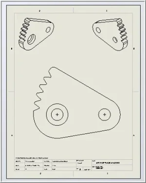
I drew this up just eyeballing your part from the pic. Actual dimensions required obviously. I think the procedure is the 'cutter' guys need a clean DXF file in order to do their thing. For example the counter bore circle would be omitted. We have forum experts who are more familiar with this stuff. I'm not saying you couldn't also just machine a pair from scratch, but I think its one of those futsy 2d profiles that lends itself to computer cutting.
 

Attachments

  • 9-12-2016 0001.webp
    9-12-2016 0001.webp
    7.2 KB · Views: 4
  • 9-12-2016 0000.webp
    9-12-2016 0000.webp
    11.1 KB · Views: 4
I drew this up just eyeballing your part from the pic. Actual dimensions required obviously. I think the procedure is the 'cutter' guys need a clean DXF file in order to do their thing. For example the counter bore circle would be omitted. We have forum experts who are more familiar with this stuff. I'm not saying you couldn't also just machine a pair from scratch, but I think its one of those futsy 2d profiles that lends itself to computer cutting.
I'm very impressed. I just do Torchmate plasma 2D (silhouette) type cutting, and could never get my mind around this stuff. I guess this is where the forum is handy and we can help each other. I think you've quickly processed what I may need here....I sure hope to get the job...if only for the fun factor.

Thanks. I will post an update when I hear from my friend. As mentioned...I'd love to get a forum member to do this. Your cad rendering really makes it jump off the page and look do-able.

P.S. I hold no grudges that you took the forum userid I would have wanted had I joined earlier...given my first name is Peter and last name starts with "T." ;)
 
A couple of tons is really not much for steel of any kind; Since it is a prototype, save yourself a lot of cost and grief, and design in enough room for larger jaws. 3/4" cold rolled plate could easily handle the loads you are talking about... Since it is a cam, the pulling force is multiplied by between 3 and 6, depending on the cam profile. Rough guessing it, using a 1" grade 8 bolt with at least 1" of 3/4 soft bar stock around it before the cam profile will easily handle the 12 tons of load. That would make your cam about 3" at the root, and about 3 1/2" to 4" at the widest point. You can rough cut the gripper jaws with hand cut plasma, and just drill a 1" hole for the bolt. No serious machining required really.

If you are really worried... up the bolt to 1 1/4" and use 1" thick material. That should handle loads over 25 tons (side pressure)... After all, a prototype will be used for a limited run to work out the kinks. BTW the wood will crush and splinter long before either of these suggestions will fail.

"Make one to throw away" - Brooks, 'The Mythical Man Month'.
 
Good advice...thanks Dabbler. I appreciate the help. I can certainly rough cut 1/2" plate on my plasma and sandwich them together as a proof of concept.
 
Back
Top