Well I like having a development environment and an IDE where I can set break points and look at variables. I realize that's not possible with real time environments. But most applications don't fit into that. So the Arduino is the Radio Shack TRS-80 or Apple-II of micro-controllers.Yes, I understand this. My first microprocessor programming adventure started before assemblers were generally available. So I actually did program in machine language.
But perhaps that's why finding the Arduino assembler output is so difficult. Perhaps it doesn't do that. Perhaps it skips straight to outputting machine language.
-
Scam Alert. Members are reminded to NOT send money to buy anything. Don't buy things remote and have it shipped - go get it yourself, pay in person, and take your equipment with you. Scammers have burned people on this forum. Urgency, secrecy, excuses, selling for friend, newish members, FUD, are RED FLAGS. A video conference call is not adequate assurance. Face to face interactions are required. Please report suspicions to the forum admins. Stay Safe - anyone can get scammed.
-
Several Regions have held meetups already, but others are being planned or are evaluating the interest. The Calgary Area Meetup is set for Saturday July 12th at 10am. The signup thread is here! Arbutus has also explored interest in a Fraser Valley meetup but it seems members either missed his thread or had other plans. Let him know if you are interested in a meetup later in the year by posting here! Slowpoke is trying to pull together an Ottawa area meetup later this summer. No date has been selected yet, so let him know if you are interested here! We are not aware of any other meetups being planned this year. If you are interested in doing something in your area, let everyone know and make it happen! Meetups are a great way to make new machining friends and get hands on help in your area. Don’t be shy, sign up and come, or plan your own meetup!
You are using an out of date browser. It may not display this or other websites correctly.
You should upgrade or use an alternative browser.
You should upgrade or use an alternative browser.
GCode alternatives
- Thread starter Janger
- Start date
I haven't yet worked with it but the Arduino IDE v2.x does provide breakpoints with certain processors. See https://docs.arduino.cc/software/ide-v2/tutorials/ide-v2-debugger
t
t
Yes. I think they listened....I haven't yet worked with it but the Arduino IDE v2.x does provide breakpoints with certain processors. See https://docs.arduino.cc/software/ide-v2/tutorials/ide-v2-debugger
t
As yet I'm still using the old one. I don't believe all processors are supported yet. I'm using the Teensy series for the Robot Arm and ESP8266 for some LED controls.
Last edited:
This CAM package doesn't appear to let the machine trajectory planner handle the arc but uses G01 linear moves.
N222 X-0.1778
N223 X-0.523 Y1.3791
N224 X-0.8379 Y1.2139
N225 X-1.1041 Y0.9781
N226 X-1.306 Y0.6855
N227 X-1.4321 Y0.353
N228 X-1.475 Y0.
N229 X-1.4321 Y-0.353
N230 X-1.306 Y-0.6855
Fusion also outputs a bunch of G01 linear moves when cutting arcs. In the adaptive tool path operations the moves are quite big and quite noticeable on the part. You have to go over the part again with another operation to get rid of the stair steps. Why do CAM programs do this instead of G02 G03 ???
I don't know. I have noticed that sometimes LinuxCNC complains about endpoints and start points not being correct. I saw that when I was playing with the hole boring program. I don't remember if I solved it. According to what I've read the most accurate arcs are created with the G2/G3 I and J mode rather than Radius R mode. I think it was the I and J points that caused the trouble.Fusion also outputs a bunch of G01 linear moves when cutting arcs. In the adaptive tool path operations the moves are quite big and quite noticeable on the part. You have to go over the part again with another operation to get rid of the stair steps. Why do CAM programs do this instead of G02 G03 ???
When I get a chance I'll check it out. Like the C command line programs from Jon Elson my Lazarus Pascal program source code is also available. So if you want to try it out I can send it to you.
So I've taken a try at this again and attached the G-Code as a .txt file.
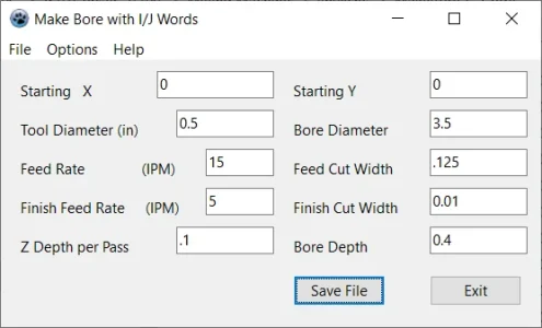
When I load the G-Code program into LinuxCNC I get this fault when it loads.
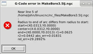
The XY locations are the same in the G-Code yet in the error above it shows different values. Must be something with the I setting of -0.0625.
N30 F15.000 X0.0313
N40 G03 X0.0000 Y0.0313 I-0.0625
Time to look at both the code and definition of G3 with I&J. Something is up. Just not sure what.

When I load the G-Code program into LinuxCNC I get this fault when it loads.

The XY locations are the same in the G-Code yet in the error above it shows different values. Must be something with the I setting of -0.0625.
N30 F15.000 X0.0313
N40 G03 X0.0000 Y0.0313 I-0.0625
Time to look at both the code and definition of G3 with I&J. Something is up. Just not sure what.
Attachments
lucsimoneau
Well-Known Member
Hey guys,
I've been teaching CNC Machining for the past 30 years at our local college and the first CNC course is called "Introduction to CNC Machining". I basically cover G-Code programming and a Mastercam introduction for the Mill and the Lathe. All in all, the course is spread out 5 hours/week for 15 weeks, so 75 hours. Of that time, 45 hours are done in the lab on the machines but the actual theory is 30 hours.
If some of you are interested, I'm willing to build an online course for you guys wishing to enter into the CNC Machining world.
At home I have a CNC Router that I use with MACH3 and a Craftex CX601 that I built a control using Centroids Acorn board and CNC12 software.
Would need to be done using Zoom or Teams, but the details could be ironed out latter if there's interest.
Could also introduce Fusion 360 if needed (or SolidWorks modeling also).
Anyone interested?
Thankyou for the well documented examples!!! I’ve learnt 10 time more about G-code seeing them.For example. I'm working on the tool change
I’m just amazed that programs can manage to generate code at all. When I think about my programming days (from nearly 30 years ago…gulp) I’m mystified at how the program is structured to achieve what it does.You have to go over the part again with another operation to get rid of the stair steps. Why do CAM programs do this instead of G02 G03 ???
That is very kind of you to offer! I have no need for G-code programming at the moment but I do appreciate that you would consider doing this for the forum.If some of you are interested, I'm willing to build an online course for you guys wishing to enter into the CNC Machining world.
historicalarms
Ultra Member
Reading codes or CNC'ing anything is never gonna be in my bag of tricks but I have to say the power feed I installed on my mill is the best money i have ever spent on anything other than the main large machines. I use it everytime I mill something weather it be for feeding at a uniform speed for cutting finish/load on the machine or for rapid return. Ive had mine for over 10 yrs and not an issue with it so far....touch wood...Don't have a power feed on any axis yet. Not sure I ever will. Too much coin I'd rather spend elsewhere.
Don't mind taking multiple passes by hand.
Main reason for power x/y axis for me would be travelling a long distance a bit quicker, not milling a part.
Definitely want Power Z though. My 20V Dewalt Drill has better things to do than sit there waiting to lift or drop the knee on my mill.
And therein lies the problem with at least MACH3 and LinuxCNC in their 'stock' form even with a pendant. I still find myself going between the keyboard for the arrow keys (XY) and the page up/dwn keys (Z) and the F3 to move between manual and the MDI screen (single G-Code text input)
My Shumatech DRO can already provide things like bolt circles. MACH3 has wizards although some you had to pay for. There are command line programs that provide G-Code (like the wizards) to run as a CNC program.
What still appears to be missing for the 'manual' oriented hobby machinist is that in between step. With more buttons than the pendants but not a full keyboard.
My ELS has 4 buttons for the Z axis. A single tap moves one increment. Press and hold it moves one increment and then moves at what would be the G01 Fxx rate. One for each axis. and the second pair move at what would be the G00 rate which is full axis speed. So maybe a keypad pattern like this:
____Y+ ____________Z+
X- ALT X+ _____A- ALT A+
____Y- _____________Z-
Edit: add _ so keypad spacing works on my android phone.
Hold the ALT down and one of the close by keys and get full speed. Otherwise like the ELS Z buttons.
Spindle would have
S+
START
STOP
S-
Then we'd have BEGIN_X, BEGIN_Y, BEGIN_Z, BEGIN_A along with the endpoints END_X...
That's 22 buttons so far.
Numeric keypad a must for manual entry of the parameters so that's another 13 buttons for 0..9, -, DEL, ENTER.
START/STOP plus some function buttons to select things like which axis to move automatically. One could add features like bolt circle for example just like the DRO has. And each START moves to the next bolt circle location. Then use the manual quill to actually drill the hole. Or have a FCN key set for Move to Next. Peck Drill. Power Tap depending on which tool is loaded.
And likely a Tool Change button with a numeric entry for the desired tool. Coolant ON/OFF, Air Mist ON/OFF.
So we're looking at a keypad of at least 40 keys and aiming for 64 might be better. This could be done on a touch screen for development but pressing and holding on a screen without the tactile feedback sucks IMHO.
Just bouncing ideas out there. Under the covers it might well be running LinuxCNC on a Raspberry Pi4 with a MESA Ethernet to I/O board. The keypad a USB connection. An MPG of course. Maybe even one for each main axis.
Now you essentially still have a manual mill. The Manual Pulse Generators (MPG) for each axis would track the pitch of the screws so that one turn is like one turn of the big handle. The DRO features so you can see where you are from either Motor position or maybe even linear encoder feedback. Use it like a manual mill but automate the tedious parts all with tactile feedback buttons.
And a system like that could start small with a simple relay for spindle ON/OFF and no speed control and only X powered motion. Then as costs and time permit adding power to the Y axis. Then a new 3-phase motor and VFD and now variable speed control.
Ultimately add a full keyboard, mouse and display and run LinuxCNC on that Raspberry Pi4.
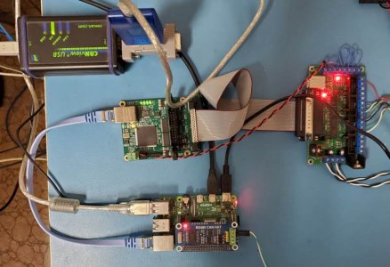
The photo is of one such setup on my test bench. Raspberry Pi4, MESA 7i92H, Breakout Board and CANUSB to talk to external devices like that full featured keypad with 64 keys and MPG. The MESA does the real time stuff. For initial playing around I can install the CAN driver in place of the X axis on my ELS and use it as that keypad with 35 keys and LCD display.
My Shumatech DRO can already provide things like bolt circles. MACH3 has wizards although some you had to pay for. There are command line programs that provide G-Code (like the wizards) to run as a CNC program.
What still appears to be missing for the 'manual' oriented hobby machinist is that in between step. With more buttons than the pendants but not a full keyboard.
My ELS has 4 buttons for the Z axis. A single tap moves one increment. Press and hold it moves one increment and then moves at what would be the G01 Fxx rate. One for each axis. and the second pair move at what would be the G00 rate which is full axis speed. So maybe a keypad pattern like this:
____Y+ ____________Z+
X- ALT X+ _____A- ALT A+
____Y- _____________Z-
Edit: add _ so keypad spacing works on my android phone.
Hold the ALT down and one of the close by keys and get full speed. Otherwise like the ELS Z buttons.
Spindle would have
S+
START
STOP
S-
Then we'd have BEGIN_X, BEGIN_Y, BEGIN_Z, BEGIN_A along with the endpoints END_X...
That's 22 buttons so far.
Numeric keypad a must for manual entry of the parameters so that's another 13 buttons for 0..9, -, DEL, ENTER.
START/STOP plus some function buttons to select things like which axis to move automatically. One could add features like bolt circle for example just like the DRO has. And each START moves to the next bolt circle location. Then use the manual quill to actually drill the hole. Or have a FCN key set for Move to Next. Peck Drill. Power Tap depending on which tool is loaded.
And likely a Tool Change button with a numeric entry for the desired tool. Coolant ON/OFF, Air Mist ON/OFF.
So we're looking at a keypad of at least 40 keys and aiming for 64 might be better. This could be done on a touch screen for development but pressing and holding on a screen without the tactile feedback sucks IMHO.
Just bouncing ideas out there. Under the covers it might well be running LinuxCNC on a Raspberry Pi4 with a MESA Ethernet to I/O board. The keypad a USB connection. An MPG of course. Maybe even one for each main axis.
Now you essentially still have a manual mill. The Manual Pulse Generators (MPG) for each axis would track the pitch of the screws so that one turn is like one turn of the big handle. The DRO features so you can see where you are from either Motor position or maybe even linear encoder feedback. Use it like a manual mill but automate the tedious parts all with tactile feedback buttons.
And a system like that could start small with a simple relay for spindle ON/OFF and no speed control and only X powered motion. Then as costs and time permit adding power to the Y axis. Then a new 3-phase motor and VFD and now variable speed control.
Ultimately add a full keyboard, mouse and display and run LinuxCNC on that Raspberry Pi4.

The photo is of one such setup on my test bench. Raspberry Pi4, MESA 7i92H, Breakout Board and CANUSB to talk to external devices like that full featured keypad with 64 keys and MPG. The MESA does the real time stuff. For initial playing around I can install the CAN driver in place of the X axis on my ELS and use it as that keypad with 35 keys and LCD display.
Last edited:
Personally I'd be interested in this. I'm competent enough on the CAD side now, but I've stayed on the sidelines of CAM/CNC mostly because I just don't have the knowledge or general background to piece together what's required, or what is best for a certain applications. I would make the time to learn & build if I had clearer line of site. Seems like prior Mach-3 guys don't like Mach-4 & others use completely different systems. Is it price induced or a function of the actual CNC application/tolerance or machine? That's where my eyeballs turn inside out. I don't know what I don't know. Even Intro or Primer sessions I suspect would generate general group interest to gauge path forward & what level of commitment you would like to offer. Maybe you could do one of those Poll/Vote things to gauge participation. Anyways, Zoom or similar would be a great format, no logistics other than getting ones butt in front of a computer. Who could turn down a generous offer like that?If some of you are interested, I'm willing to build an online course for you guys wishing to enter into the CNC Machining world.
At home I have a CNC Router that I use with MACH3 and a Craftex CX601 that I built a control using Centroids Acorn board and CNC12 software.
Would need to be done using Zoom or Teams, but the details could be ironed out latter if there's interest.
Could also introduce Fusion 360 if needed (or SolidWorks modeling also).
Anyone interested?
Hi @lucsimoneauHey guys,
I've been teaching CNC Machining for the past 30 years at our local college and the first CNC course is called "Introduction to CNC Machining". I basically cover G-Code programming and a Mastercam introduction for the Mill and the Lathe. All in all, the course is spread out 5 hours/week for 15 weeks, so 75 hours. Of that time, 45 hours are done in the lab on the machines but the actual theory is 30 hours.
If some of you are interested, I'm willing to build an online course for you guys wishing to enter into the CNC Machining world.
At home I have a CNC Router that I use with MACH3 and a Craftex CX601 that I built a control using Centroids Acorn board and CNC12 software.
Would need to be done using Zoom or Teams, but the details could be ironed out latter if there's interest.
Could also introduce Fusion 360 if needed (or SolidWorks modeling also).
Anyone interested?
I’d love to see some photos and commentary on your 601cx cnc conversion. I’d love to see in person but where are you located?
John
Former Member
Guest
I find a fast way of learning (or at least editing and understanding GCode) is seeing with a viewer.
NCviewer is a online free version and GWizardE is a paid stand alone version.
What they do is let you see the code as you scroll through the lines and at the same time see the actions they cause.
I use a conversational language from Centroid to create the GCode and then edit (remove the conservative portions of the code to optimize the code for faster run times), typically I can reduce run times by 10-20%.
More sophisticated software (ie Mastercam and others) do this as well and better from the get go but at a cost that is very high.
There are lots of ways to create G-Code. From the CAD programs or some write special functions. This one I translated from a C language command line program where you had to type in all the parameters to a Lazarus Pascal that will run on all sorts of different platforms.
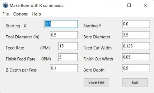
The Save File button creates a .ngc file for LinuxCNC. I've attached that as a .txt file.
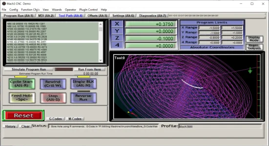
I can then load that into MACH3 running on my laptop and trace through the G-Code steps watching the path in white.
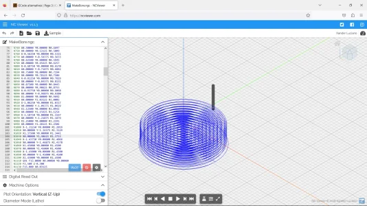
Here's what it looks like with that free G-Code viewer. Shows the tool but doesn't show each path preview.

The Save File button creates a .ngc file for LinuxCNC. I've attached that as a .txt file.
I can then load that into MACH3 running on my laptop and trace through the G-Code steps watching the path in white.

Here's what it looks like with that free G-Code viewer. Shows the tool but doesn't show each path preview.

Attachments
Yeah i am interested. I have a bit of experience but I learn something new almost everyday.Anyone interested
Former Member
Guest
@jcdammeyer , here is a copy of the GCode Generated by Centriod's Intercon conversational language to compare.
