• Spring 2024 meetup in Calgary - tentative date Saturday, April 20/2024. Other regions are also discussing meet ups. If you want one in your area get going on organizing it! discussion
  • We are having email/registration problems again. Diagnosis is underway. New users sorry if you are having trouble getting registered. We are exploring different options to get registered. Contact the forum via another member or on facebook if you're stuck. Update -> we think it is fixed. Let us know if not.
  • Spring meet up in Ontario, April 6/2024. NEW LOCATION See Post #31 Discussion NEW LOCATION

G3616 Conversion.

jcdammeyer

John
Premium Member
What is the make/model of the servo? I'd like to find the spec sheet and connections for it.
The web site is really slow at the moment.
http://en.bergerda.com/product/596.html
This is for the SDD04NK7D Servo drive which is mated to my 60SM-M0130NAL 400W motor. The drive is about 6"x6"x2"
The SDD20NK9D Servo drive mates to my 110SM-M0630ZAL 1.8kW motor and is about 8"x6.5"x3"
 

Attachments

  • 110SeriesACServoMotor.pdf
    407.2 KB · Views: 0

YotaBota

Mike
Premium Member
JC - Thanks for the offer but I'm going to wait on replacing the motor for now and just get to know the machine. If a factory Y drive from a CNC conversion comes up at a decent price I would consider that.
 

jcdammeyer

John
Premium Member
No problem. I'm not ready to order anything until the basic conversion is complete. And I'm somewhat stalled at the moment because a bit of angle iron I milled shows how the X axis backlash affects the curving cuts. Now in this case it's not important but it did enough to send me on a tangent to look into ball screws again and then considering the work that would involve sent me onto a tangent upgrading my ELS firmware.

Long and short of it I have touched the CNC conversion for two weeks and I promised myself I'd finish it before I took on or restarted any other projects. So, it's back to the mill and the keyboard/mouse/monitor mount and the plates for the spindle motor and pulleys.

The lift hook CNC path was tested in a bit of scrap angle so ignore the small holes. The second one I cut on the other side was not quite as nice as the backlash mucked up the cut a little.

The hooks go over the studs which will be welded into the crucible so I can lift it out, pivot the handle, hook to a tab at the bottom and pour both the castings for the top motor mount and the 4th axis motor mount.
 

Attachments

  • CrucibleLiftHook-1.jpg
    CrucibleLiftHook-1.jpg
    189.4 KB · Views: 0
  • CrucibleLiftHook-2.jpg
    CrucibleLiftHook-2.jpg
    185.7 KB · Views: 0
  • CrucibleLiftingStud-1.jpg
    CrucibleLiftingStud-1.jpg
    91.7 KB · Views: 0
Last edited:

kevin.decelles

Jack of all trades -- Master of none
Premium Member
Please start another thread for the crucible project ! I’m very interested


Sent from my iPhone using Tapatalk
 

jcdammeyer

John
Premium Member
This thread seemed the most appropriate and it's 2 years old with only one posting but the title is appropriate
cnc, pattern, mold & aluminum casting
 

jcdammeyer

John
Premium Member
So the casting of the first plate is complete with the new crucible and lifting/pouring shank. Total weight of aluminium was 12 lbs with it all sitting on the bathroom scale. I then cut off the sprue and risers, drilled 6 holes at T-Slot width and then went through the laborious process of flattening the plate. Somehow the casting was thicker in the middle and thinner on two opposite corners.

I had to shim it up to not wobble and still remove as little as possible. I also discovered that the fly cutter bit I'd been using since the Gingery Lathe days was part of the problem with poor surface finish. Of course by then I'd already finished.

Anyway, the plate was both wider and longer than I could machine in one pass in X and Y. So initially while it was warped lots of pivoting around of the head and moving the head in and out.

Then clamped cross ways to edge the end. I still need to make it the correct width to line up with the edges of the mill casting. At the moment it's about .25" too wide. The casting didn't shrink as much as I expected and I scaled up the pattern 3%.

Now to cast the motor plate that sits on the mount plate and pivots to adjust belt tension.
 

Attachments

  • MountPlateEdge-1.jpg
    MountPlateEdge-1.jpg
    117.3 KB · Views: 0
  • MountPlateSurface-2.jpg
    MountPlateSurface-2.jpg
    123.8 KB · Views: 0
  • MountPlateSurface-1.jpg
    MountPlateSurface-1.jpg
    114.9 KB · Views: 0

jcdammeyer

John
Premium Member
Oh and as the above photo shows the fly cutter was the middle size one from a Busy Bee Tools set with a 1/4" Cemented Carbide lathe bit. Turns out for the loading it would flex and vibrate. And the mill had moved out of tram by about 0.005". So I trammed the mill to within about 0.0005" (tilted in the other direction now) and mounted the big vise that was able to clamp a discarded casting that failed.

I then found a HSS 5/16" lathe bit and touched it up to be more like what was suggested on various forums and youtube videos. I also mounted it in the larger fly cutter body and had it extend less. The surface finish is beautiful and shows that this casting hadn't been degassed very well as there was a fair amount of porosity. But gorgeous otherwise.

Short CNC program to face off the whole with with a final depth of cut of 0.002", 390 RPM with the 2" 'diameter sweep and 2 IPM.
 

Attachments

  • TestFlycut_3.jpg
    TestFlycut_3.jpg
    99 KB · Views: 0
  • TestFlycut_4.jpg
    TestFlycut_4.jpg
    88.2 KB · Views: 0

jcdammeyer

John
Premium Member
So the motor mount plate is finished. Just need to run out tomorrow and pick up some 12mmx30mm bolts for the pivot. Then remove the original motor and mounting plate. I'll use it with a transfer punch to set where the bolt holes go to fasten the new plate to the top. Hopefully I have the right size belt. If all goes well by the weekend I'll have 0v-10v control of the spindle turning from 0 to 3000 RPM. No more belt changes. Yahoo!
 

Attachments

  • MotorPlateAssembly.jpg
    MotorPlateAssembly.jpg
    110.8 KB · Views: 0

jcdammeyer

John
Premium Member
Been kind of busy over the last couple of months. The new pulley for the servo motor was cast and turned with the longer shaft extension. I've been able to have LinuxCNC control motor speed and switch from 1:1 to 3:1 for the belt drive.

Now I want to close the loop and add an encoder to the spindle. There isn't room using the 4 step pulley which sits on a tapered cone. So I'm building a new pulley that is just two step and will allow me to add a slotted disk for the encoder.

I had to build a tapered cone arbor that matched the unknown taper on the mill. Turns out it's 3 degrees from vertical which means I use the 6 degree setting on the South Bend taper attachment. I did a trial with a piece of cast aluminium which was too small and then used a piece of 2.375" stock to make the good one. It's got a 19mm hole with a key for the arbor I used to make the motor pulley.

Then machine the pulley blank using the same settings as the arbor. Blank fits tightly on the spindle cone and on the arbor. But not pleased with the pulley. Probably the worst casting I've ever poured with respect to porosity. Odds are I'm going to use this one as a practice one to make sure I have the tooling all figured out.

I'll post a picture of the finished sample.
 

Attachments

  • SpindlePulleyRawCasting.jpg
    SpindlePulleyRawCasting.jpg
    139.7 KB · Views: 0
  • Arbour-2.jpg
    Arbour-2.jpg
    118.2 KB · Views: 0
  • SpindlePulleyBuild-2.jpg
    SpindlePulleyBuild-2.jpg
    81.5 KB · Views: 0
  • SpindlePulleyBuild-1.jpg
    SpindlePulleyBuild-1.jpg
    77.4 KB · Views: 0
  • SpindleMotorPulley-5.jpg
    SpindleMotorPulley-5.jpg
    91.6 KB · Views: 0

jcdammeyer

John
Premium Member
Here are a few more photos of the process. You can see that I've removed the original 4 step pulley and how the drive is with that tapered cone.
MillSpindleCone.jpg

The motor pulley was also turned on the lathe. The hardest part was the difference in size between the two steps. Made it very difficult to get access. I moved tool post a lot. And swapped the arbor end for end a number of times so that I could keep the compound set at the one angle rather than swing it back and forth.
TurningMotorPulley-1.jpg

Cutting the 6mm keyway wasn't easy but I used a 3D printed guide. That worked well enough for the motor pulley casting but the Arbor for the Spindle pulley was round bar stock. The type that creates long spirals while turning. And I ended up using a hammer to pound the broach through. A 3T press isn't strong enough for a 2.25" long 6mm key way.

I used the same approach for the tapered arbor as I did for the motor pulley. Once the key way is cut, drill with #7 and tap for 1/4" set screw.
Keyway.jpg
 

Attachments

  • TurningMotorPulley-2.jpg
    TurningMotorPulley-2.jpg
    96.7 KB · Views: 0

jcdammeyer

John
Premium Member
Here's the new spindle motor pulley mounted and turning the spindle.
NewPulleys-1.jpg
I've turned a shoulder on the bottom of the pulley to make room for an encoder disk. This was the whole point of replacing the original. There's no room for a disk or toothed belt to an encoder on the original nor do I really need a 4 step pulley. In fact it's unlikely I even need the second with the AC Servo.

EncoderDisk.jpg
With the encoder I can close the loop in LinuxCNC and I'll only know when when I start power tapping at slow RPM if I need that second reduction ratio.
 

jcdammeyer

John
Premium Member
Bee a while since I posted. In the last 6 months or so my Gecko drive for the knee failed again. To be more precise the connector overheated probably because the PC board inner traces are damaged. This is the second connector that turned black. So I ordered a replacement Stepperonline from amazon.ca for $80 with free prime shipping. It was awful. 3.6kHz annoying whine. Ultimately the support was along the lines of it must be your motor.

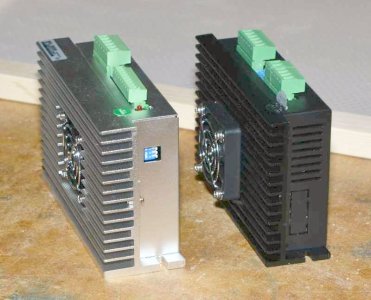
I've had some success with the Bergerda products from China so I ordered a couple of 6A stepper drivers from them. All in all with FedEx it turned out they were $2 more expensive, have a bigger heatsink, metal cover instead of plastic and no whine.

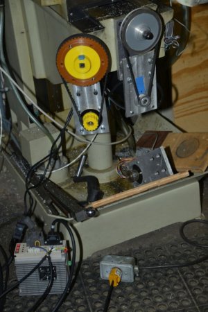
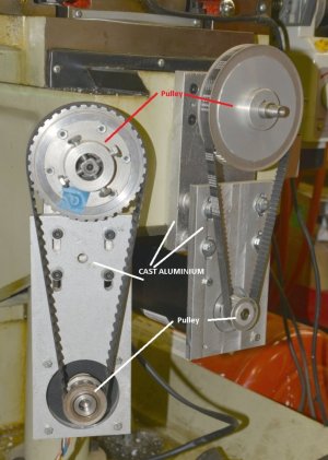
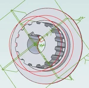
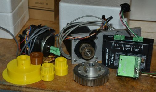
Meanwhile I also had ordered an AC servo to replace the stepper motor on the knee so I'd get more than 25 IPM. Turns out with a 19mm shaft on the motor the 12T pulley wouldn't fit. So for now I've 3D printed new pulleys to give me a 3.2:1 ratio. The plan is to go metal once I create the tool bit with the correct profile.

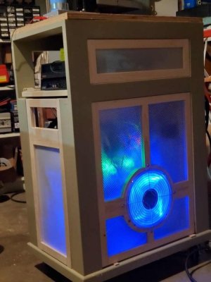
Meanwhile I'm working on closing in the CNC cabinet. With all the openings I was always worried I'd get chips flying onto something and toasting it. So out comes the drill press mortising tool and the table saw tenon jig after sitting unused for probably 10 years. Need to sand and paint them yet. The plastic panels are ceiling lamp fixture panels. Translucent for everywhere except for the one with the fan.

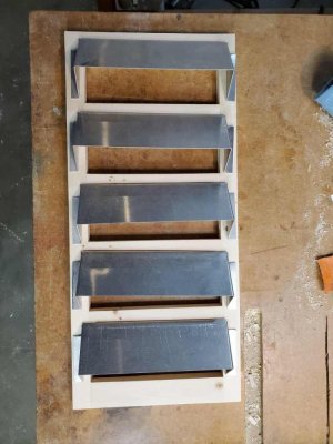
The wires come out the back and I used my 3:1 metal tool to make these vent covers so the wires and air can be fed out. The vents still need mounting holes. And still a door for the front of the PC tray.
 

Attachments

  • KneeServoDrive.jpg
    KneeServoDrive.jpg
    117.3 KB · Views: 8
  • LitUpCabinet.jpg
    LitUpCabinet.jpg
    94 KB · Views: 8
  • GluedandTrimmed.jpg
    GluedandTrimmed.jpg
    120.7 KB · Views: 6

kevin.decelles

Jack of all trades -- Master of none
Premium Member
I would be interested in more details on your pulley setup . I have a very similar mill that is using stepper motors w/lead screw . I 3d printed my pulleys as well. So far so good

I did not do the z axis, choosing to do the quill instead

Curious on how the 3d parts attach to the shafts with sufficient strength


Sent from my iPhone using Tapatalk
 

jcdammeyer

John
Premium Member
I would be interested in more details on your pulley setup
Curious on how the 3d parts attach to the shafts with sufficient strength
The upper horizontal shaft to the bevel gears had the bushings replaced with ball bearings at both ends since pulley drive stresses in one direction. The ball bearing mount at the bevel end also took out more of the end play but there is still some backlash.
The original pulley I used with the stepper motor used 4 screws to clamp onto the 4 sides of the square handle drive part. YAxisMachining-8s.jpg
The stepper motor just had a flat for the driving pulley setscrew. The 3D printed version still has the 4 screws but I printed the square hole and it's a nice firm sliding fit onto the square shank. The screws now just hold it in position. Yo.u can see that in the previous photo of the setup. If you want I can make a closeup photo of it.

The new motor is 19mm with a 6mm key so I 3D printed at 15T pulley that has a large enough ID for the 19mm hole and 6mm key. I then reamed and broached the key channel with the broach to make it fit the motor shaft and a set screw through a raised tooth holds it tight.
Pulley15TKeyed.jpg
I 3D printed a second flange for the front and glued it in place.
These are the left over bits and pieces after all that.
MillKneeExperience.jpg

Had I procured the Bergerda Stepper drive first (which didn't take any longer than Prime) I'd not have gone through it all. You can see the size of the heatsink difference in the photo. And it's just better built for only a few dollars more. Even $20 more would still be $60 less than the Gecko it replaced. Notice too on the Bergerda the connector for the control signals is a different size from the stepper/power connector so there's no chance of accidentally plugging power into control which is possible with the Stepperonline.com product.
StepperDrives-3s.jpg
I did want faster knee travel so in the long run changing to the Bergerda AC Servo will be a good thing. But so much extra work.

The other up side of changing to the Bergerda AC Servo is I already have 220VAC in the cabinet so I can totally get rid of the huge toroid etc. used to power the single 1200 oz-in stepper.
 

kevin.decelles

Jack of all trades -- Master of none
Premium Member
Thx for the details. I found that relying on set-screw on a flat was problematic (slippage), and this was on the aluminum gears. I now have 90% of it on key'd shaft, and where I don't, I went with two set screws.
 

jcdammeyer

John
Premium Member
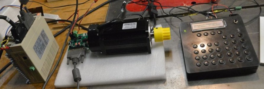
I never did have issues with the single set screw on the Stepper Motor flat for the knee. But the motor never made it past about 240 RPM. Changing over to the Bergerda AC servo was very exciting even if a pain as far as the pulleys were concerned. I set it up on the bench as shown in this photo.
BergerdaTest.jpg
The Drive on the left has 220VAC wired for power. Above that the wires to the motor. The Black DB-25 is the motor encoder and the grey goes to that small interface board. Now the drive can take single ended open collector type drivers but for longer distances and noise immunity is better with differential signals.

I designed a small interface board that takes the 5V TTL signals from the break out board and translates them to differential step/direction/enable. The FAULT signal back from the drive is also intercepted and redirected back through a separate header.

On the RHS is one of my ELS units in a 3D printed box. No labels on the buttons since I have them memorized. I used the ELS to test various steps/rev values and speeds. Since I have 3.2:1 on the pulleys and each hand crank moves 0.250" I can set two parameters inside the the drive to have an effective steps per rev to result in 0.00025" positioning.

The pulley on the motor is the 12T pulley but it needed that large shoulder and that puts the pulley teeth too far out for alignment with the driving pulley. That's why I had to go to 15T and 48T. I really wanted 4:1 so I may still go to a finer pitch belt and pulley setup to create 4:1.

BTW, that motor is 750W which implies 1HP at 2000 RPM. Amazing.
 

jcdammeyer

John
Premium Member
Thought I should update where I am on this conversion. The AC Servo has been in for a while now. There were some issues that showed up when I added about 100 lbs onto the table. For some reason the backlash compensation resulted in LinuxCNC reporting a following error. We suspect it was electrical noise trashing a UDP ethernet packet resulting in a missing message. Once I properly set the STEPGEN_MAX_ACCEL to 2x the MAX_ACCELERATION value the problem went away. Here is a Z Axis Motion. youtube video. I'm waiting for metal pulleys. Seeing a buildup of black material (probably from the belt) on the yellow driving pulley. Ratio is 3.2:1 to 0.25" pitch acme screw through a bevel gear. Hence the noise. Max speed is 150 ipm. The new pulleys are HTD with rounded tooth profiles compared to the square L series.
 
Top