G12

Janger

(John)
Administrator
Vendor
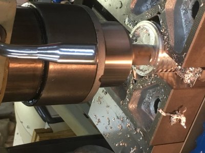
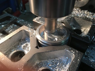
G12 command mill a circular pocket love it!
 

Attachments

  • 5CD86933-9861-48B2-9B0E-5FFCC72FD038.jpeg
    5CD86933-9861-48B2-9B0E-5FFCC72FD038.jpeg
    128.1 KB · Views: 16
  • BD03C89E-53A1-481C-8089-0F56E9295F76.jpeg
    BD03C89E-53A1-481C-8089-0F56E9295F76.jpeg
    142.3 KB · Views: 16

PeterT

Ultra Member
Premium Member
Cool! How do the diameters compare in opposing axis?
Also, I've always wondered - in CNC toolpath programming, do you tell it to climb mill vs conventional mill, or can you switch at some point between roughing & finishing?
 

Janger

(John)
Administrator
Vendor
G12 is clockwise and G13 is counter clockwise. So you can choose conventional or climb.
G12 I<diameter> F<feedrate>
simple command. Specify the diameter with the I parameter. It assumes the tool is located in the center, it moves to the diameter of I at feed rate F and then moves through the circle. After 360 deg it moves back to the center. Assumption is it is on the xy plane. I'm not sure I answered your question.

There are also much more sophisticated options: good ref is here: http://www.cnc-training.com/tandp/jun04.htm
 

PeterT

Ultra Member
Premium Member
Sorry, my Q2 wasn't clear. I used to hear (predominantly from the homebrew CNC router types) that if they miked across the X-axis they would get a slightly differnt measurement than Y-axis. Something to do with steppers or resolution or Cam or phase of the moon... For example X = 1.000 and Y= 0.998" in other words a slight elipse. Thats what I was wondering, if you measured it & how it came out. (And what you do about it if its not truly circular like from a boring head).
 

Janger

(John)
Administrator
Vendor
I’m measuring 2.070” one way and 2.0695 the other way. It’s a bit different but as accurate as my calipers.... setting the backlash compensation is important. I’m pleased actually. This is not a fancy mill.
 
Top