• Spring 2024 meetup in Calgary - date Saturday, April 20/2024. discussion Please RSVP Here to confirm and get your invitation and the location details. RSVP NOW so organizers can plan to get sufficient food etc. It's Tomorrow Saturday! you can still RSVP until I stop checking my phone tomorrow More info and agenda
  • We are having email/registration problems again. Diagnosis is underway. New users sorry if you are having trouble getting registered. We are exploring different options to get registered. Contact the forum via another member or on facebook if you're stuck. Update -> we think it is fixed. Let us know if not.
  • Spring meet up in Ontario, April 6/2024. NEW LOCATION See Post #31 Discussion AND THE NEW LOCATION

Ferro brand 10" X 50" mill brought back to life.

John Conroy

member
Premium Member
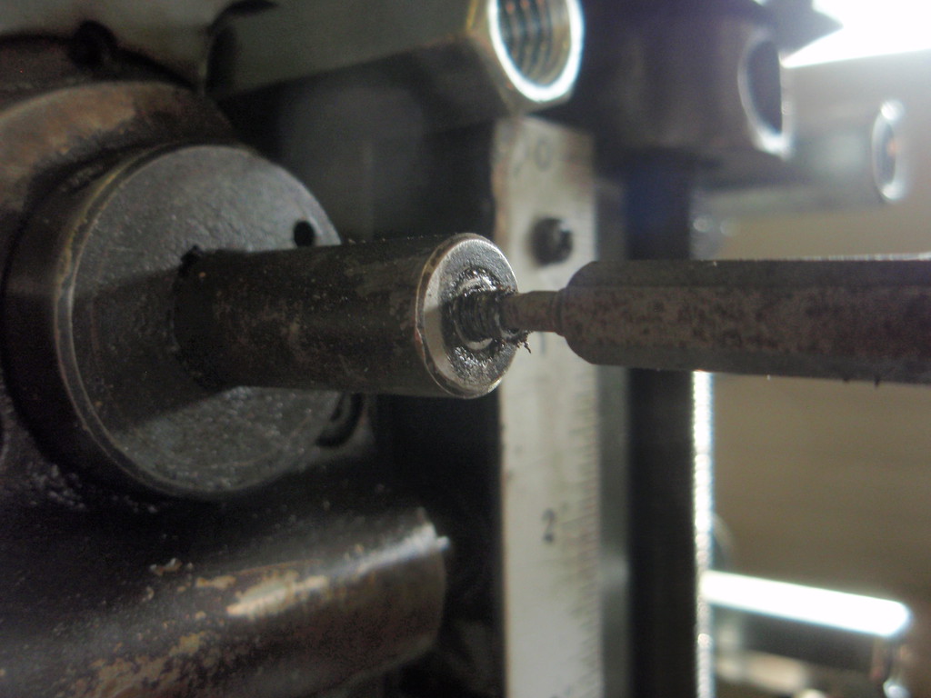
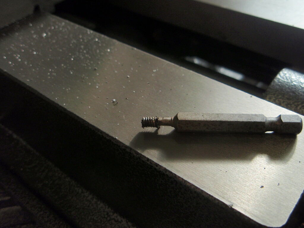
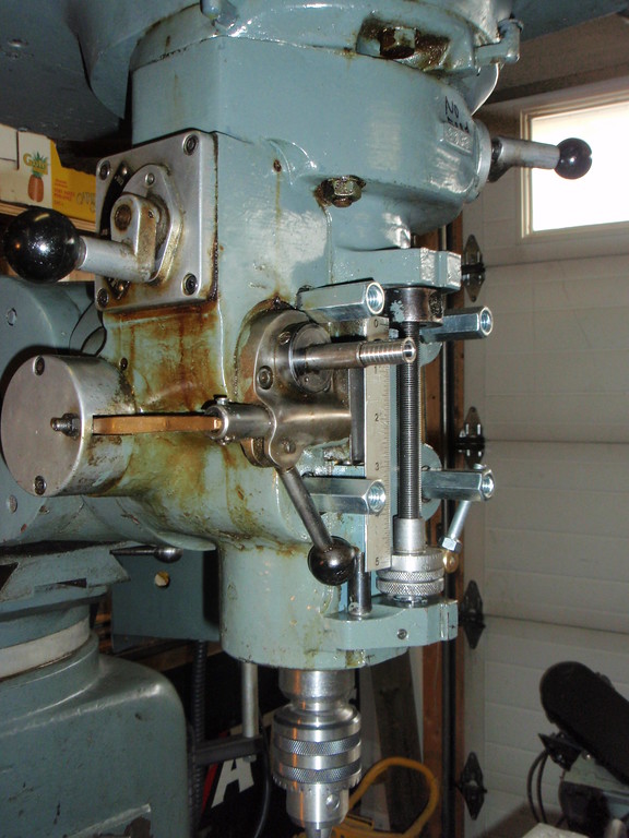
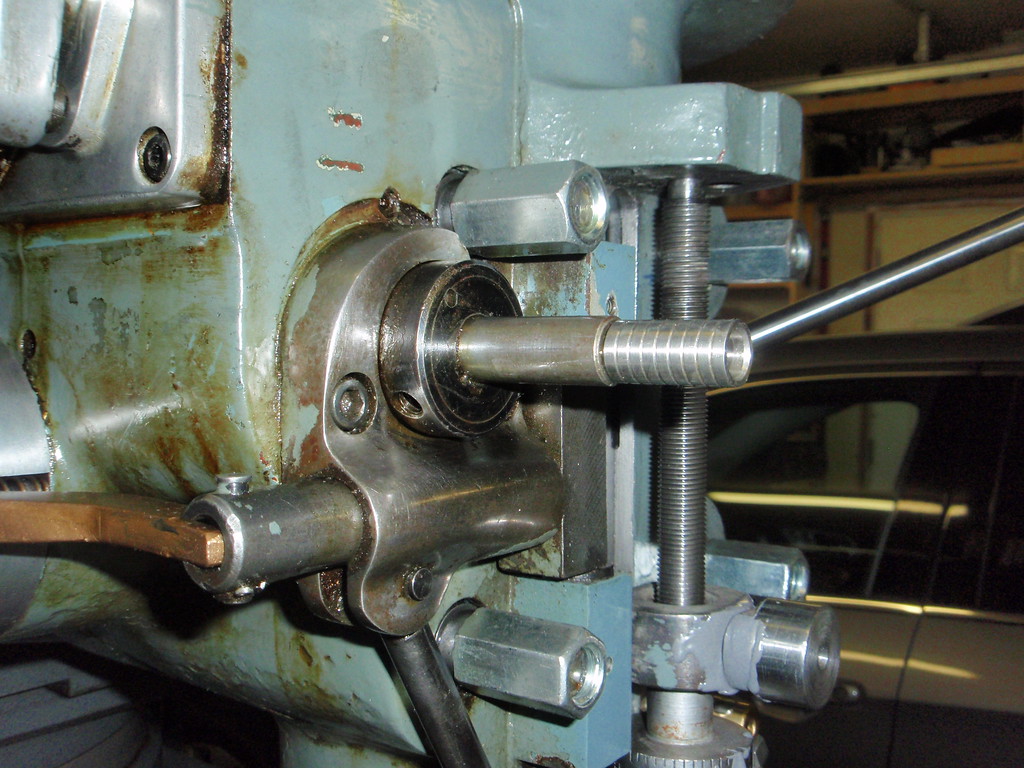
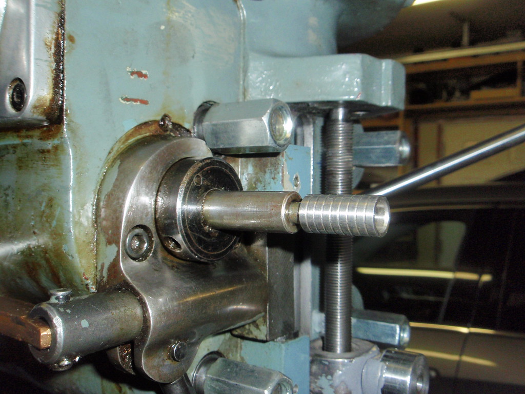
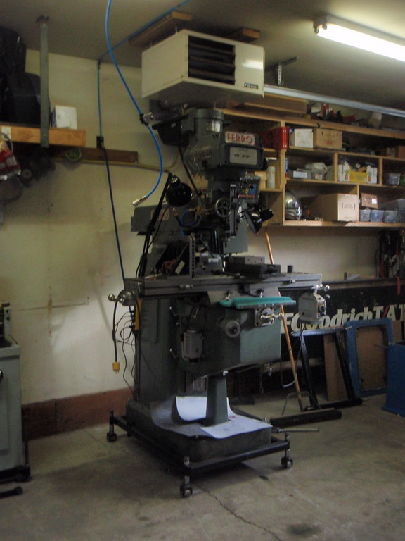
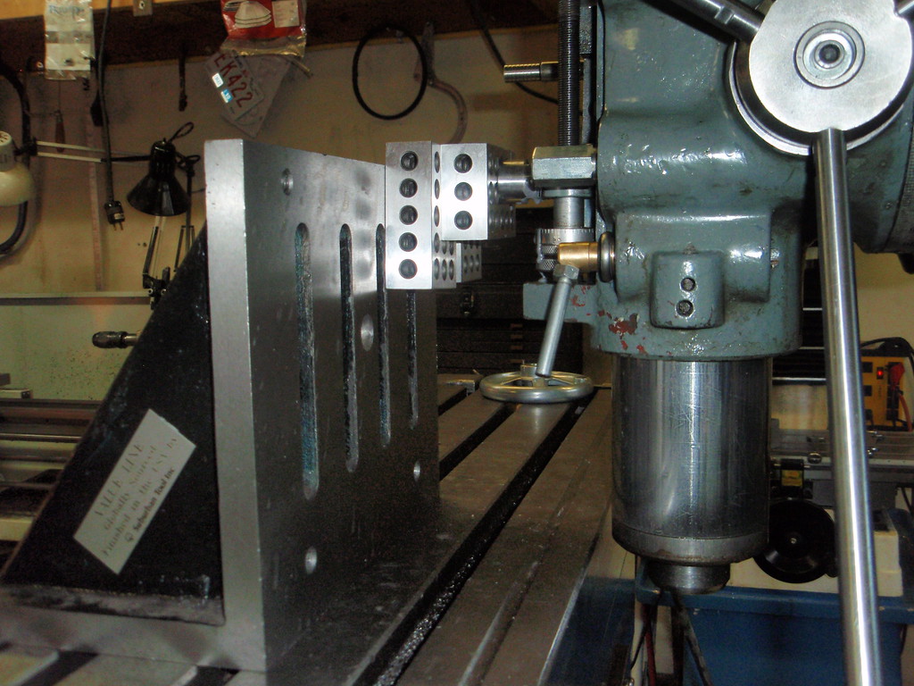
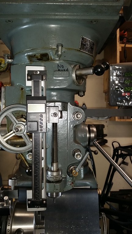
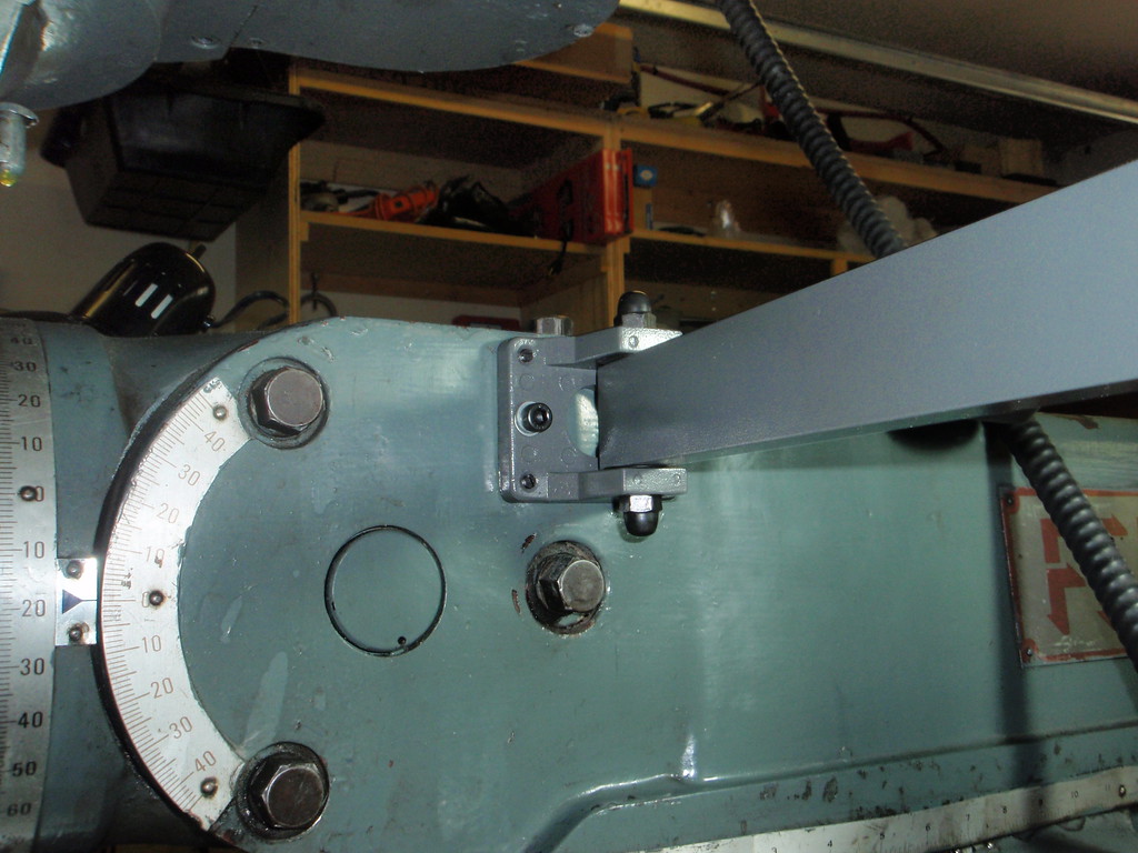
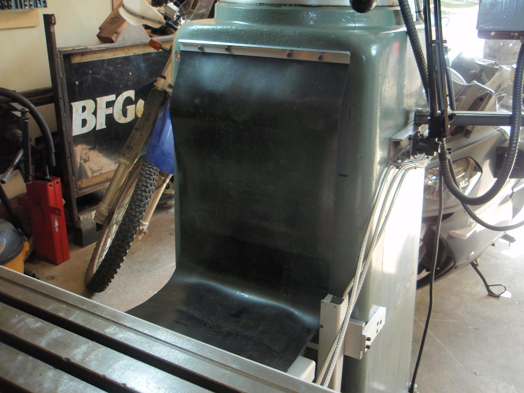
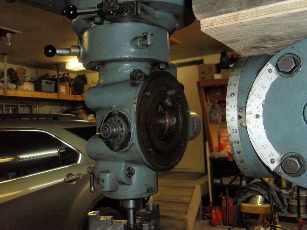
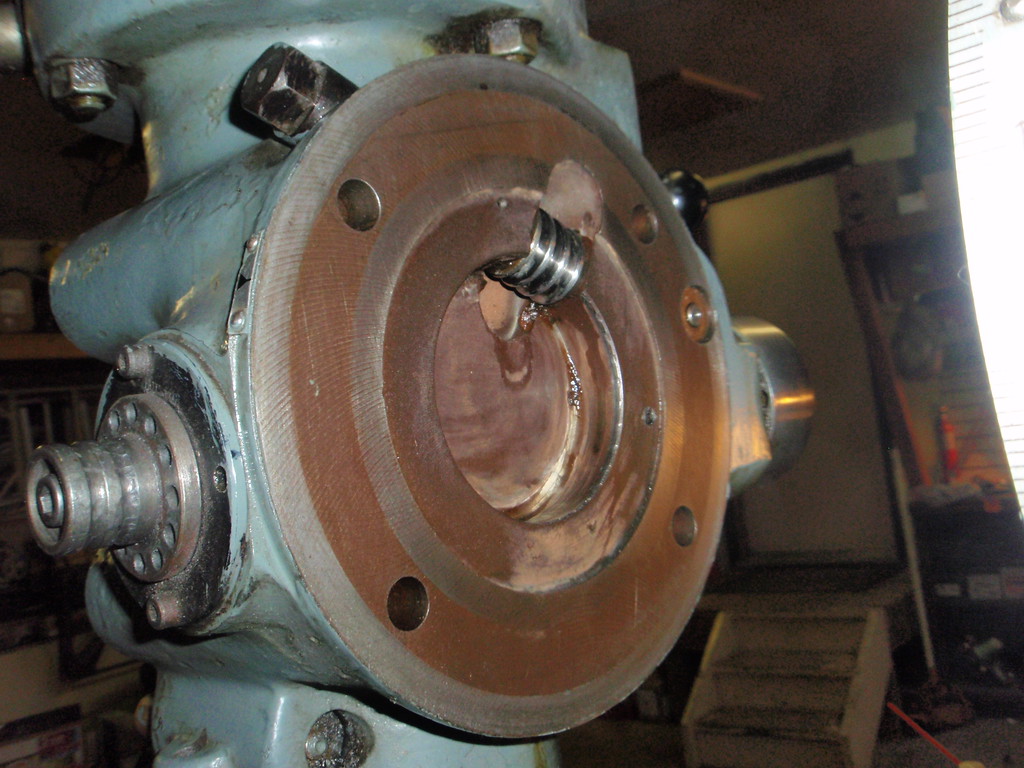
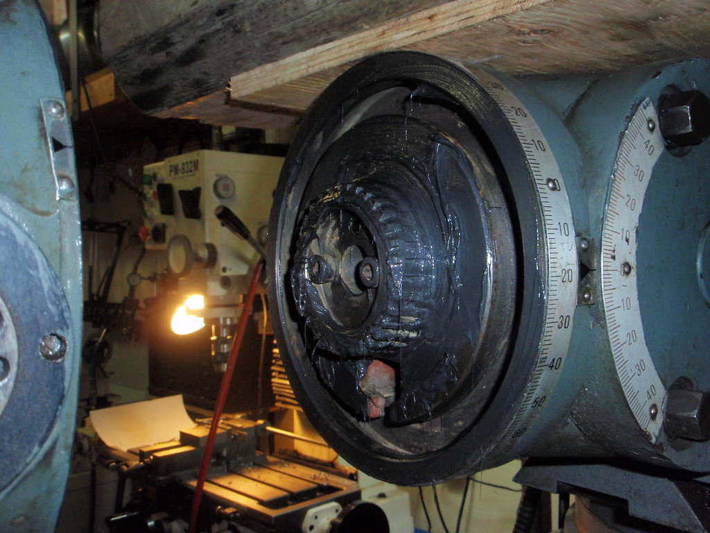
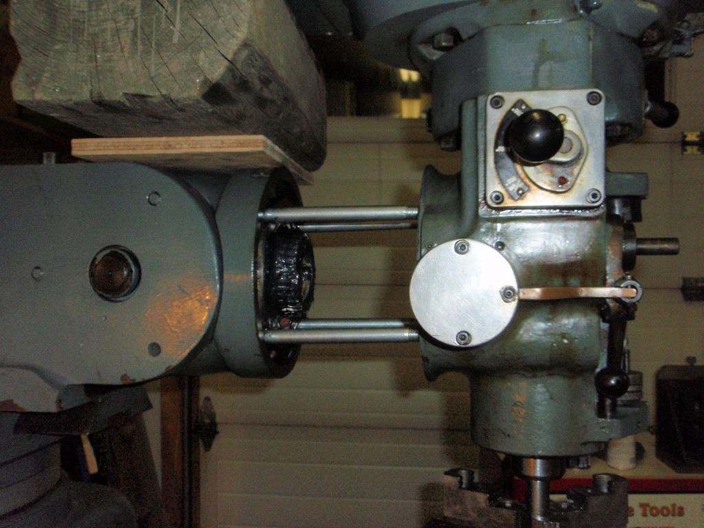
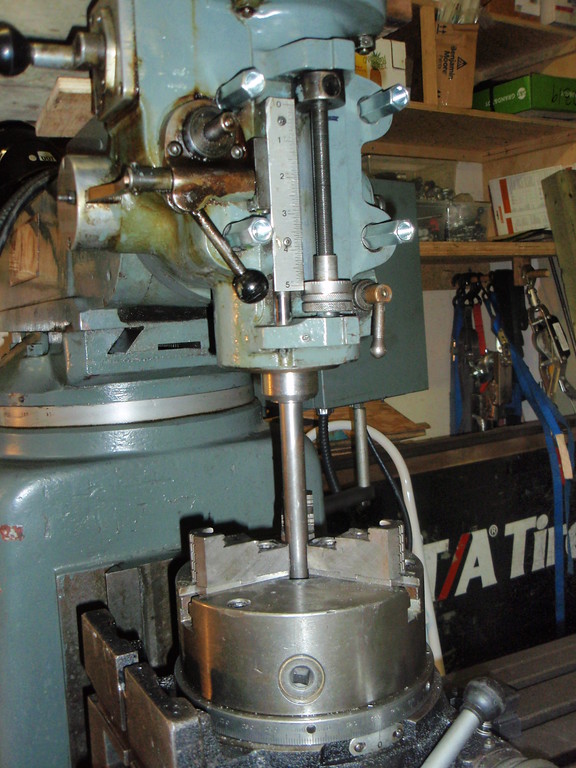
To carry on with the repairs, I found that 1 of the 4 bolts that holds the head to the ram was broken off. They are 1/2" by 7" with square heads so I had to order them from the bolt supply place. I used my Vertex super spacer and a 7/8" rod in a collet to move the head away from the ram. I put a small piece of plywood on the table in the center hole of the super spacer chuck and put the 7/8" rod in the chuck with the rod projecting all the way to the bottom and resting on the plywood on the table and tightened the chuck. I put a 7/8" collet in the spindle and raised the knee so the rod entered the collet and tightened it up. With the spindle all the way to the top of its travel and the spindle clamp tight I loosened the 3 remaining bolts holding the head to the spindle and raised the knee slightly to release the pressure on the bolts. Then I used the Y axis to move the table outward and bring the head away from the ram. The table has a 800lb weight capacity and the super spacer and the head weigh about 500 combined so I wasn't too worried about damaging anything.. I slid in the new bolts and cleaned and lubed the worm gear that allow tilting the head side to side and the reversed the process. Once I was started the head was away from the ram for about 15 minutes.

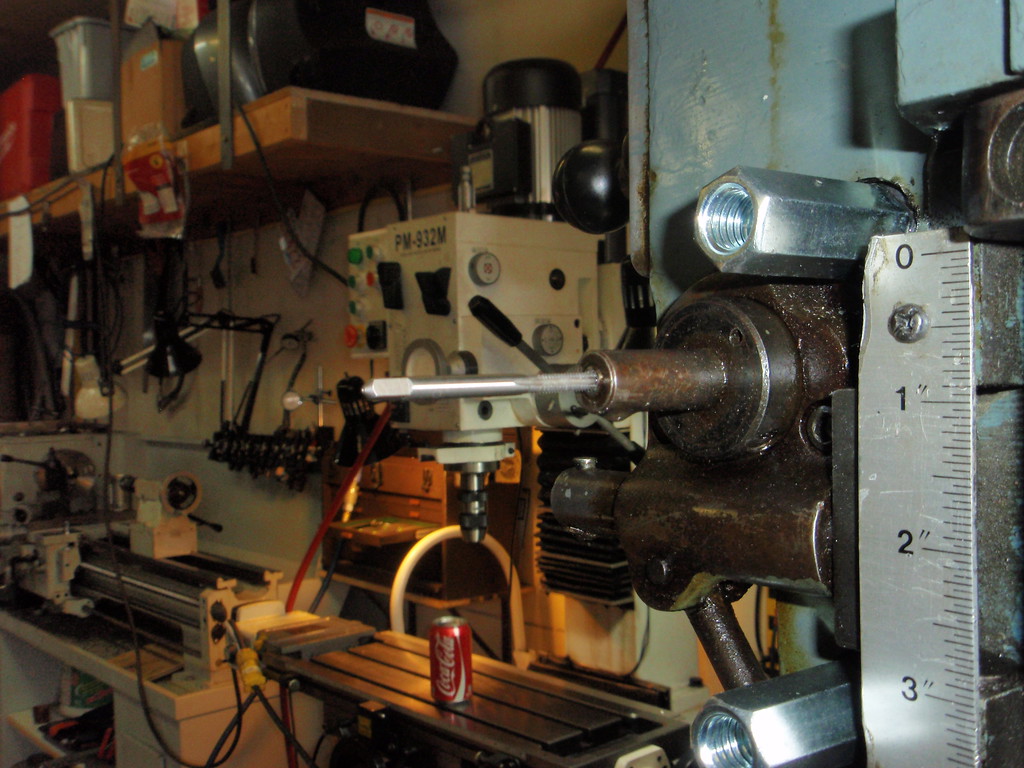
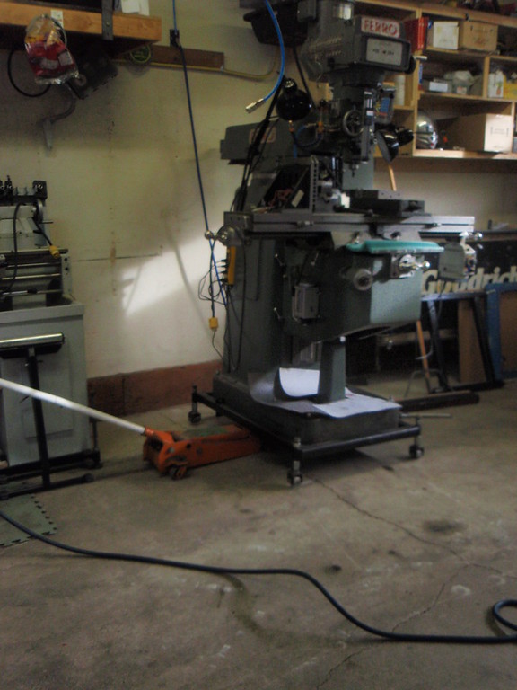
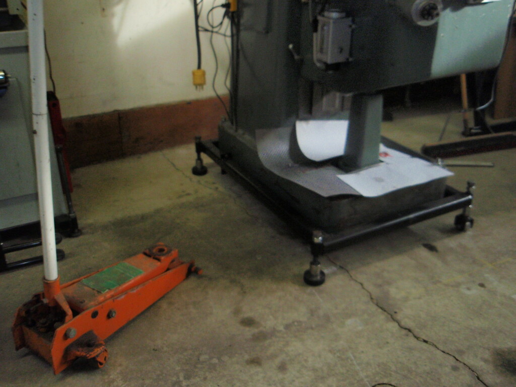
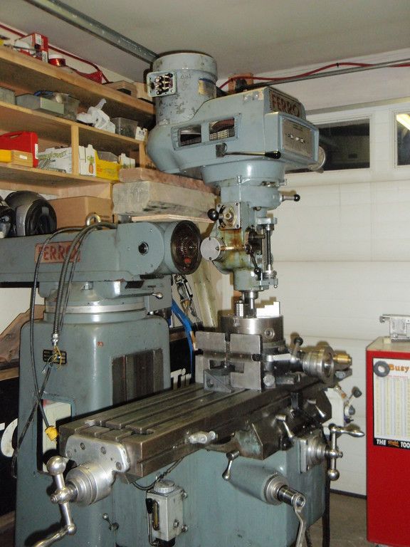
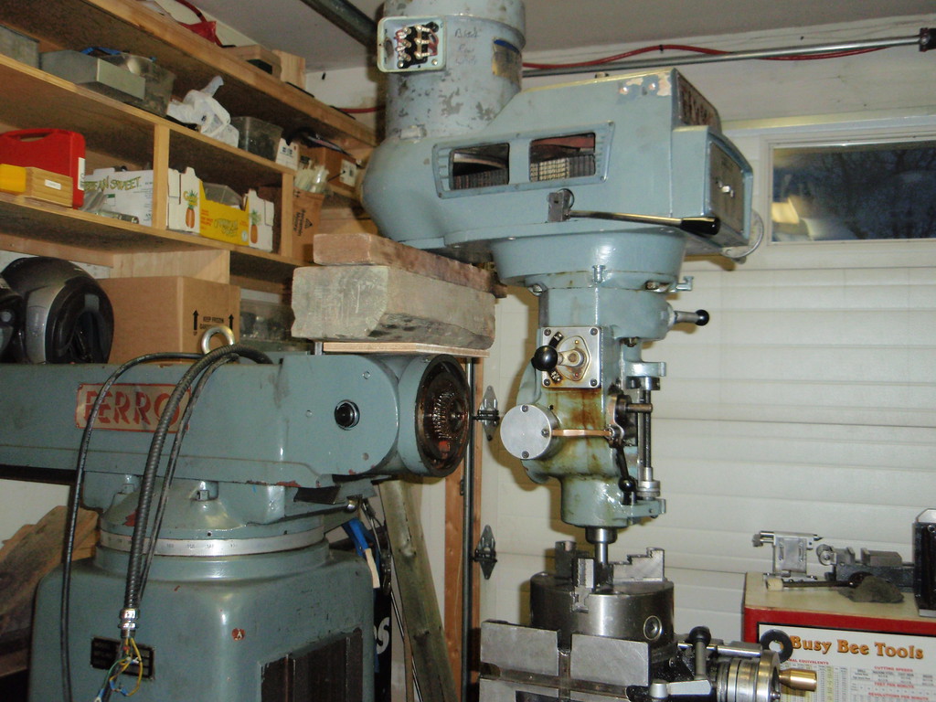
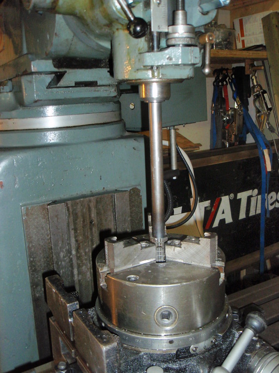
OK I was a little nervous as you can see I slid some wood blocking under the head but it really didn't do anything as the set up was very solid without it.


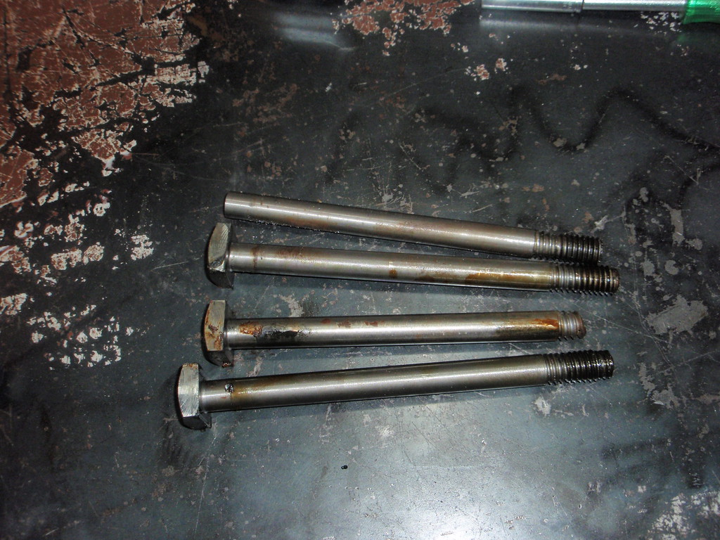
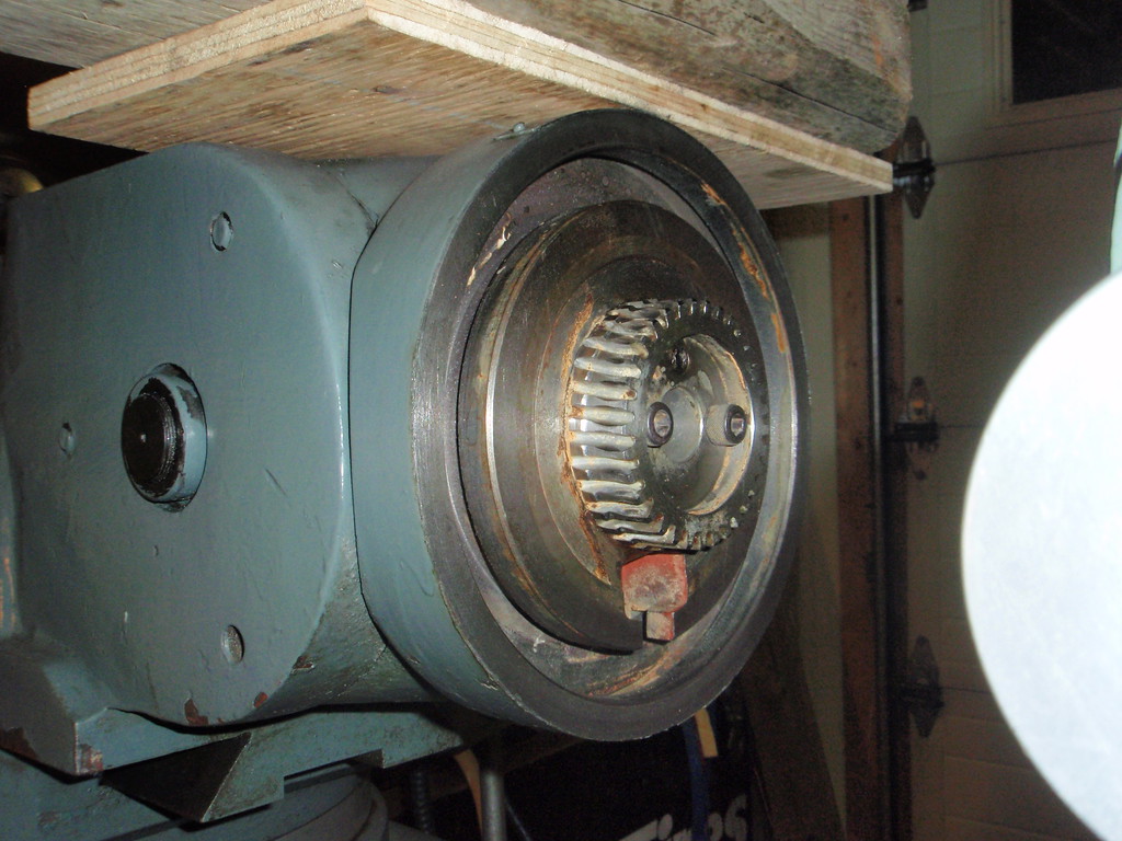
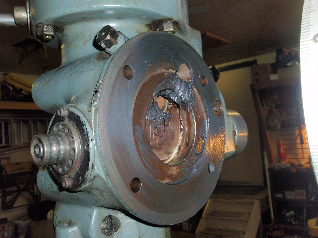
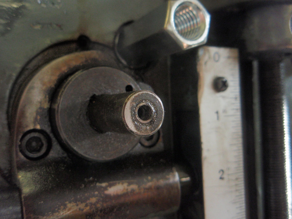
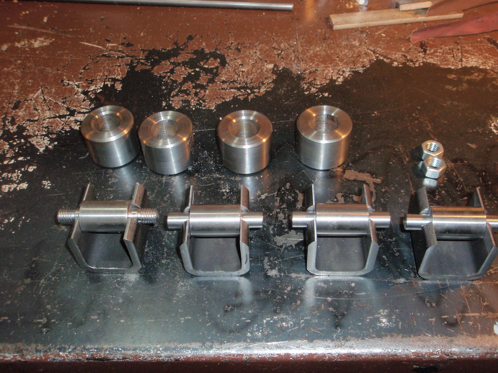
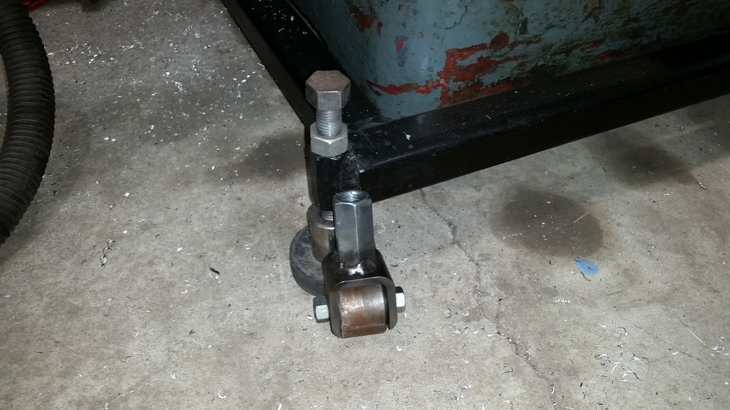
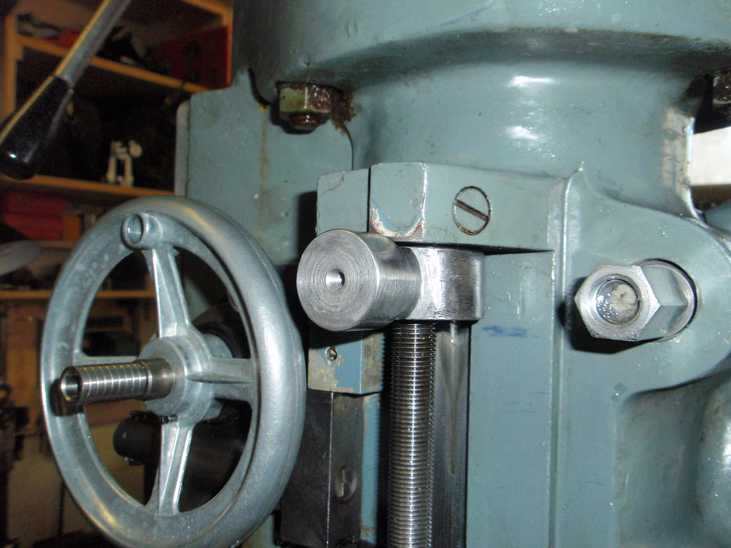
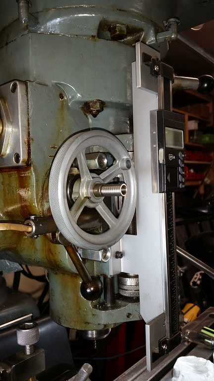
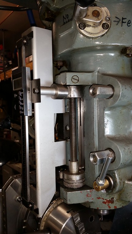
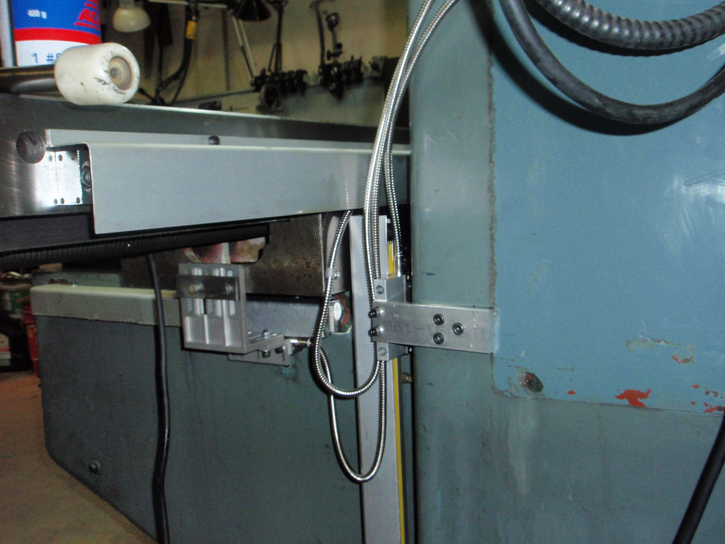
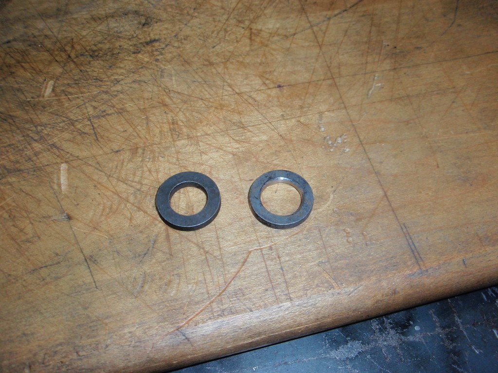
I used some hardened washers from big block Chevy head bolts opened up to 1/2" from 7/16" and long nuts to engage all the thread on the 7" bolts. I smeared lots of moly grease on the worm gears.


Then I loosened the chuck on the super spacer and lowered the knee, all done!


John Conroy

member
Premium Member
The m5 screw in the end of the power down feed direction change shaft was broken off and the little pull handle was missing. I drilled a 1/8" hole in the center of the screw and then found that my smallest easy out was broken so I used a #1 Robertson screw driver bit and tapped it into the hole and the screw turned out easily. I chased the thread with a tap and made up a new handle. With the handle pushed inward the power down feed goes down and with it pulled outward the feed goes up. The hand wheel was missing too.


New handle installed.


Last edited:

John Conroy

member
Premium Member
As I said earlier I wound making a heavy duty set of wheels to move this beast around. Some 2" square tubing with 1 side removed. Some solid steel wheels with 2" OD and 1" ID and axles with 1/2" nuts on the ends. These thing will not bend! A good coating of moly grease and the machine rolls pretty easily on them.


To move it into it's final resting place I jacked up 1 side at a time and thread the wheels onto the 3/4" threaded rod I have for leveling. I use a floor jack with the axle cradle removed to do the lifting. When the machine was out in the middle of the shop I lifted the front first then the rear but after I rolled it back to the wall I lifted 1 side then the other to remove the wheels.


I had to move the Ferro out of the way so I could get my small PM932 mill out of the way.


I just turn the wheels in the direction I want to go and use a long pry bar against the floor and bottom of the stand to get it rolling.


I used machined cups under the threaded rod for a solid foot for leveling and then added hockey pucks under those for vibration dampening.
 
Last edited:

John Conroy

member
Premium Member
I added a quill travel DRO starting with using epoxy to bond a threaded boss to the quill stop piece that travels with the quill. I used the existing hole you can see in the first pic and machined a boss to fit in the hole and used some blocks and an angle plate to get it square and let it set overnight. I also picked up a 4” hand wheel and drilled a hole for a pin to match the one on the face of the power down feed flange. I had to turn a little off the OD of the hand wheel to clear the scale and I knurled the OD while it was in the lathe.


I made the mounting bracket from a length of 2.5” aluminum tube and got the scale at KMS tools. The quill has 5” travel so I bought a 6” scale.


Last edited:

John Conroy

member
Premium Member
I made some stainless sheet metal grilles for the head to replace the broken plastic ones.


A little too shiny for this old girl but they will get dirty soon enough.
 

John Conroy

member
Premium Member
After using the mill for a year or so I decided I like it enough to invest in a 3 axis DRO. I bought a Sinpo brand on ebay and it has been trouble free and accurate for a reasonable cost.


I won't bore you with all the details of installing the scales but it was an all day job to get them square to the travel of all 3 axis within .002". Lots of drilling and tapping and making custom brackets.


PeterT

Ultra Member
Premium Member
John, I read through your power knee lift pictorial again.
Is it safe to say all of these units will require drilling cross hole through shaft for the drive gear (roll pin)?
Any reason to think brand X might be different than brand Y - ie. you buy a different unit in the future & the hole no longer lines up? Or that can be accommodated by different shims?
Does the power drive in any way prevent ability to re-set the dial to a new reference position?
 
Last edited:

PeterT

Ultra Member
Premium Member
I noticed you use the limit switches on power X travel. I am a bad boy & mine is hanging behind the mill. I use my homemade 2-position hard stop quite often & I don't want to give that up. I guess the downside is I cannot invoke power feed & then go answer the phone :) Have you figured out a way to integrate or are your limit switches triggering accurately enough that you trust them to stop consistently? Seems to me when I tested this it was kind of spongy +/- too much for my liking.
 

Attachments

  • SNAG-9-11-2018 0005.jpg
    SNAG-9-11-2018 0005.jpg
    30.1 KB · Views: 1

John Conroy

member
Premium Member
The kit comes with an extension for the existing z axis shaft. It threads onto the existing shaft that has 34" 16tpi threads. According to Matt at Precision Matthew's most of the Taiwanese mills use the same threads and this kit will fit them. He asked me to check my mills thread size before ordering. I'm pretty sure the kits are all very similar no matter the brand. The only part that would wear would be the bronze gear and its keyed to the shaft, not pinned so it could be easily replaced.

I never use the limit switches and i never thought of making a hard stop in place of them. Great idea! Now I've got another project.
 
Last edited:

Dabbler

ersatz engineer
Be careful that you hard stop doesn't jam the drive. The gears are vulnerable to stripping if jammed while the servo is still turning!
 
Top