• Spring 2024 meetup in Calgary - date Saturday, April 20/2024. discussion Please RSVP Here to confirm and get your invitation and the location details. RSVP NOW so organizers can plan to get sufficient food etc. One week to go! More info and agenda
  • We are having email/registration problems again. Diagnosis is underway. New users sorry if you are having trouble getting registered. We are exploring different options to get registered. Contact the forum via another member or on facebook if you're stuck. Update -> we think it is fixed. Let us know if not.
  • Spring meet up in Ontario, April 6/2024. NEW LOCATION See Post #31 Discussion AND THE NEW LOCATION

Ferro brand 10" X 50" mill brought back to life.

John Conroy

member
Premium Member
Since it's a cold rainy day I thought I would re-do my old post about the re-furbishing of my mill. The original post was deleted after the great Photobucket debacle.

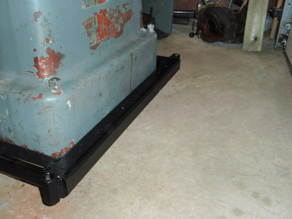
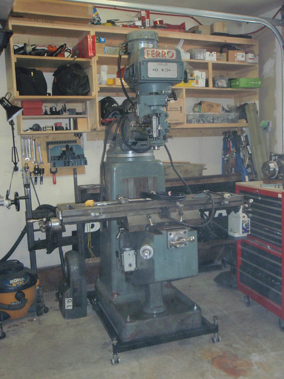
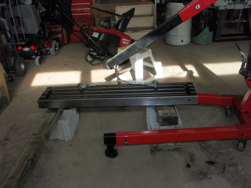
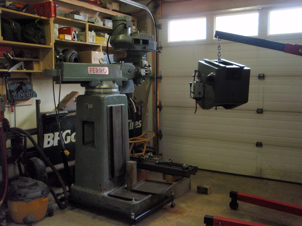
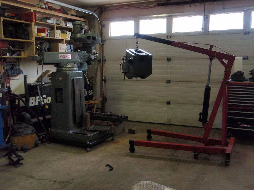
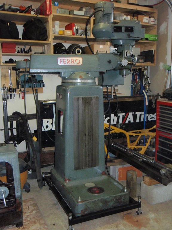
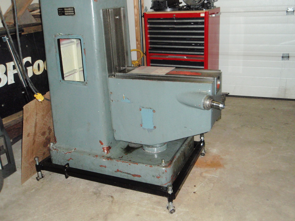
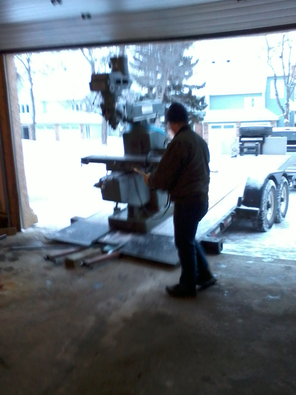
I had been looking for a bigger milling machine than my current PM932PDF and finally ran across a “Ferro” branded Taiwanese Bridgeportclone locally. I borrowed and tilt deck car trailer on just about the coldest day of winter (February of 2015) and brought it home with the help of my friend Darcy. It was a challenge getting this 2500 lb machine loaded and unloaded but we got it done. This is the only picture I took that day, I just plain forgot to take any others as I was stressed and cold.


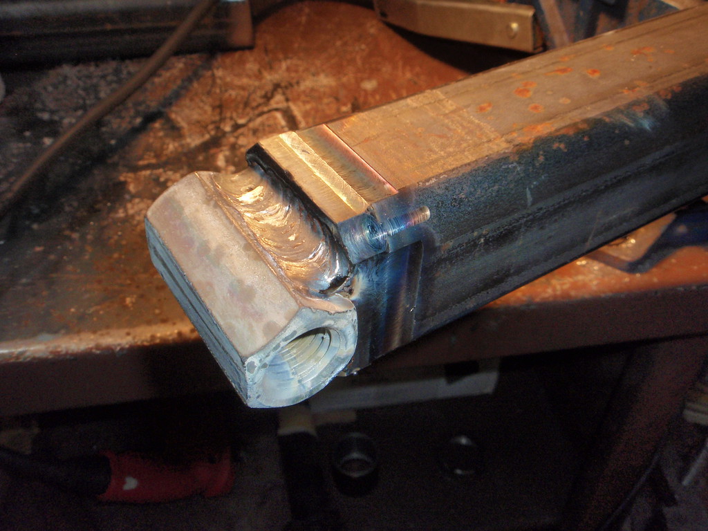
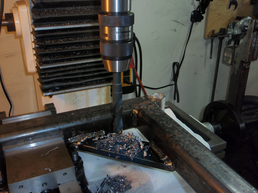
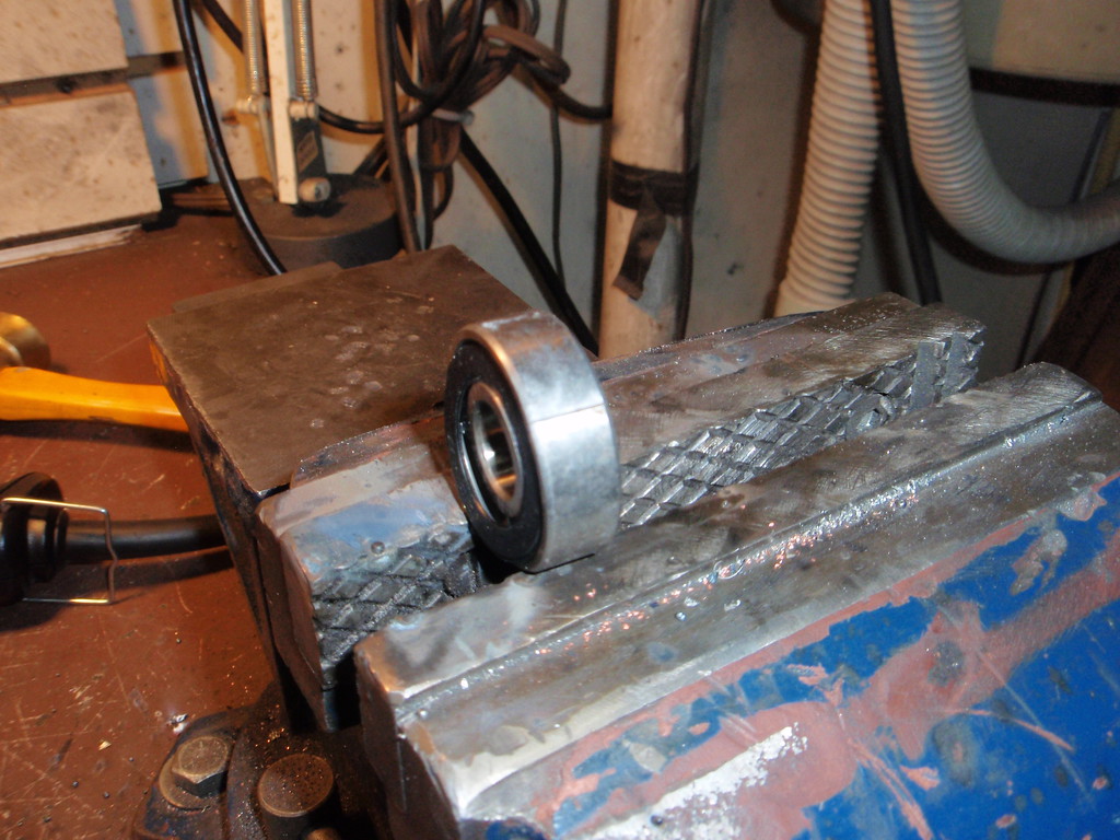
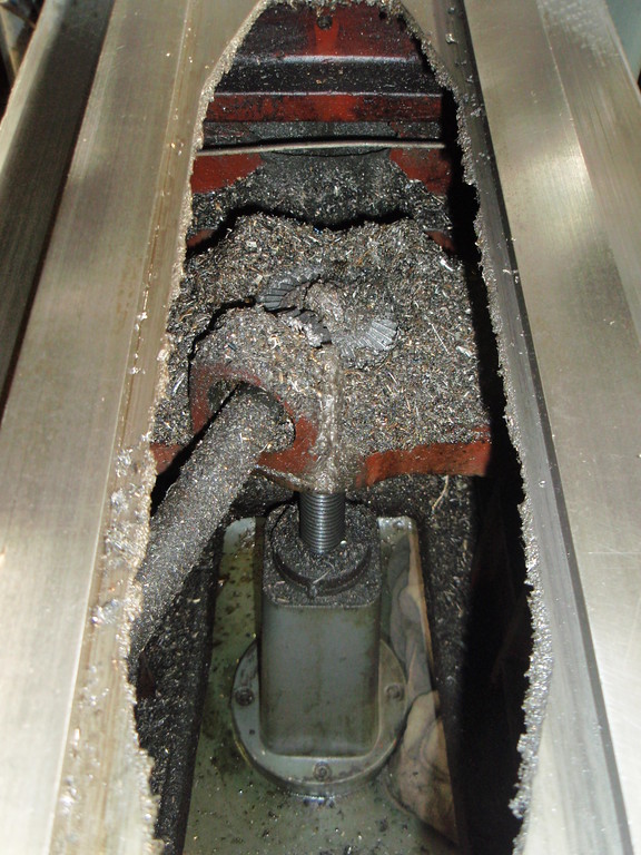
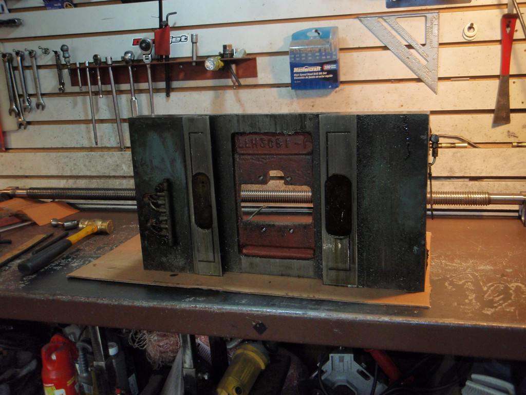
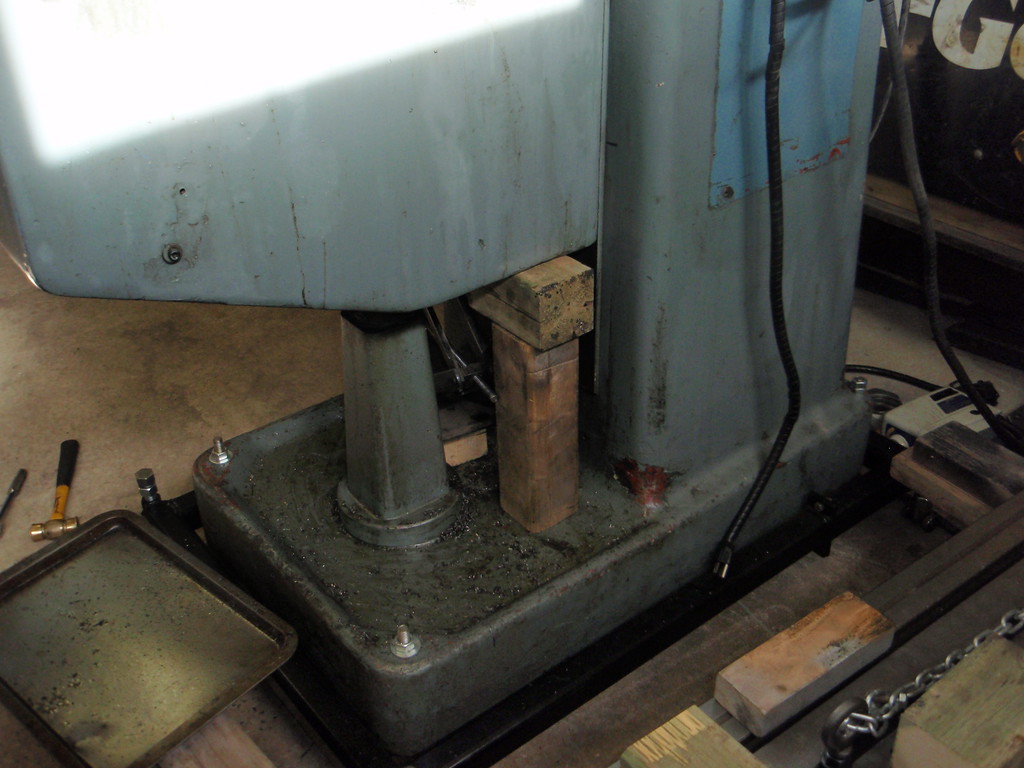
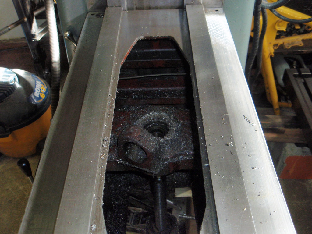
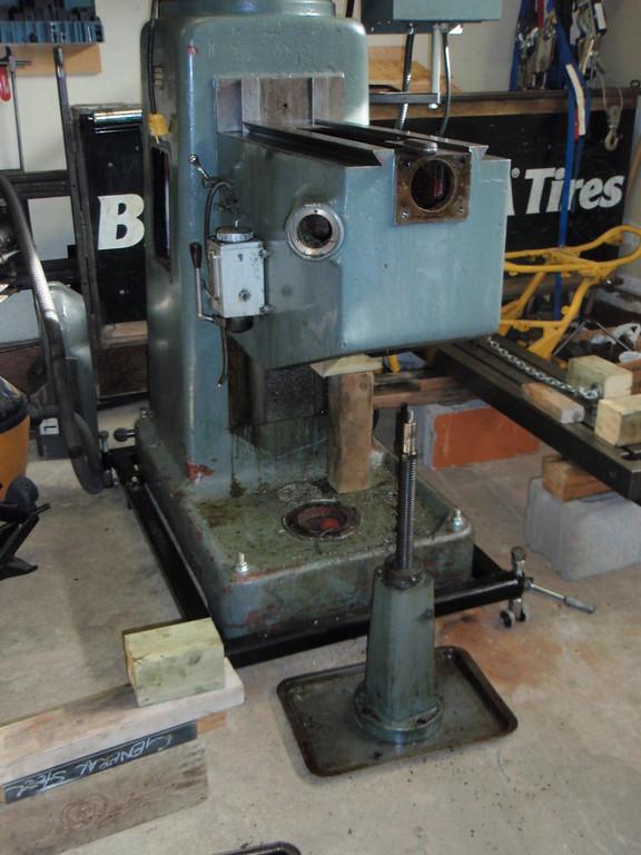
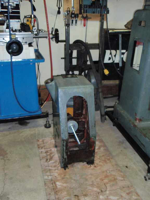
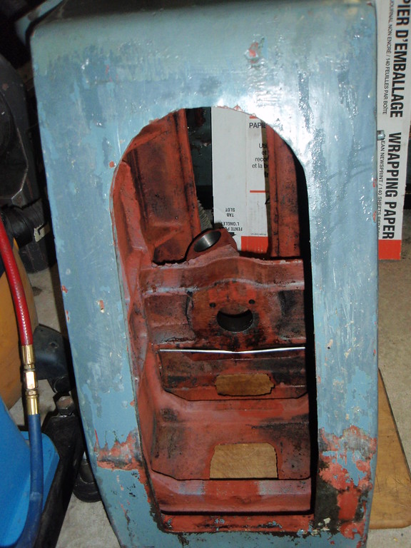
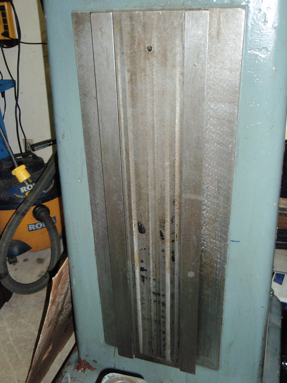
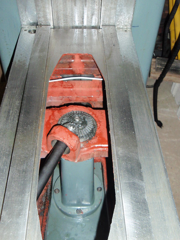
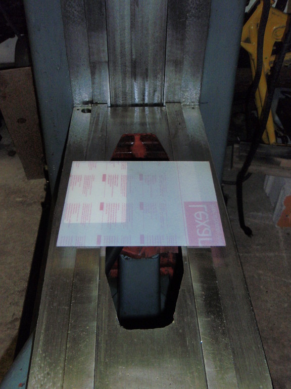
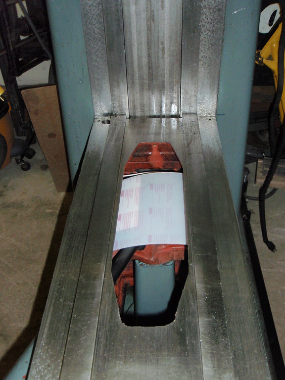
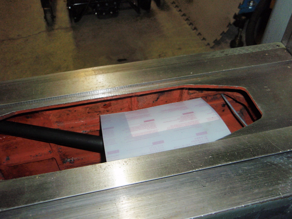
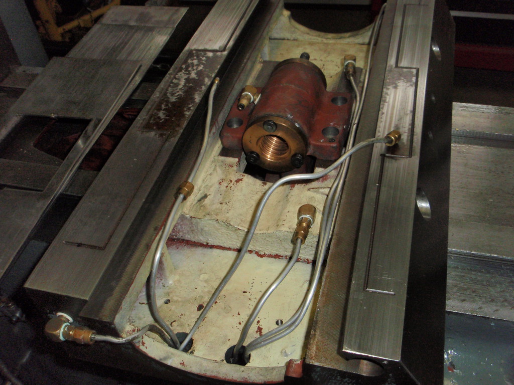
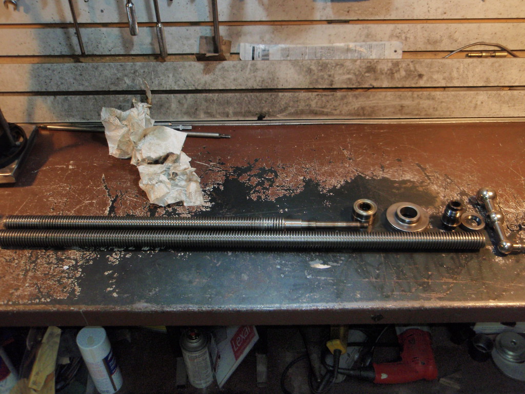
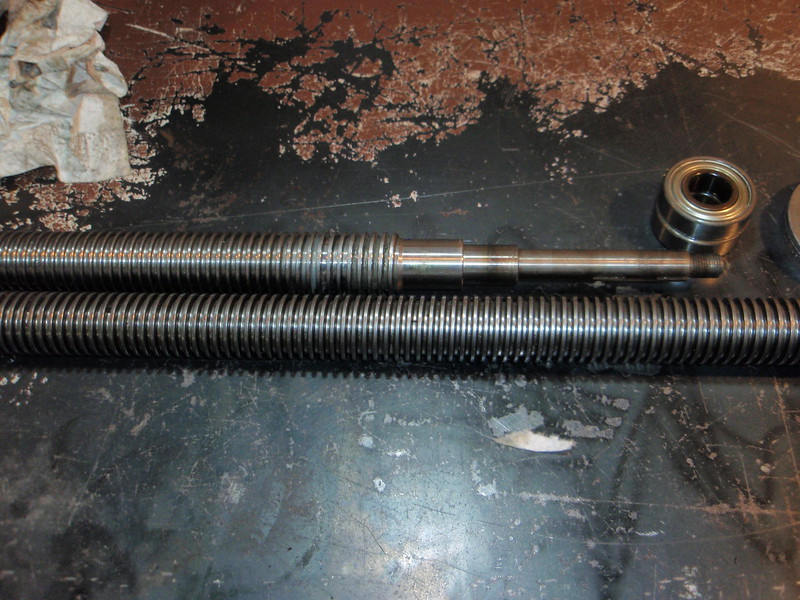
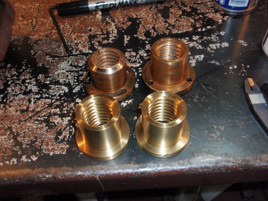
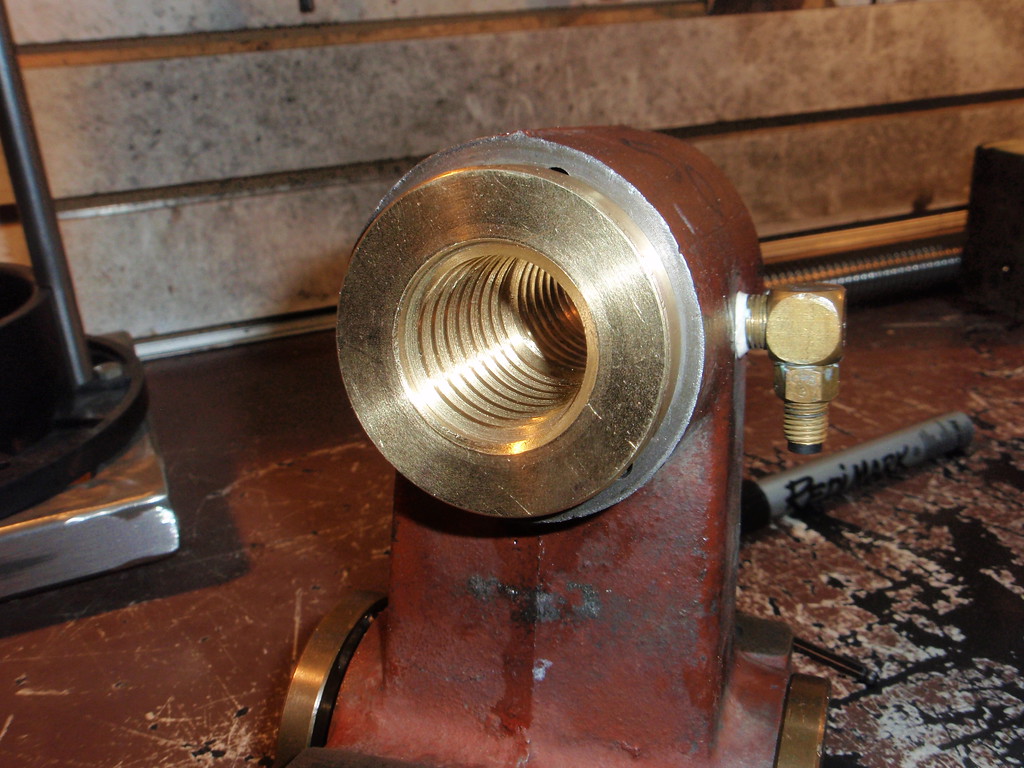
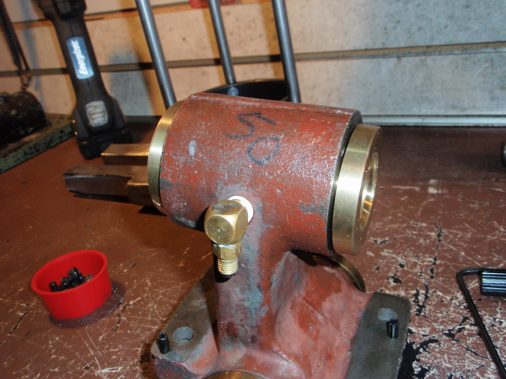
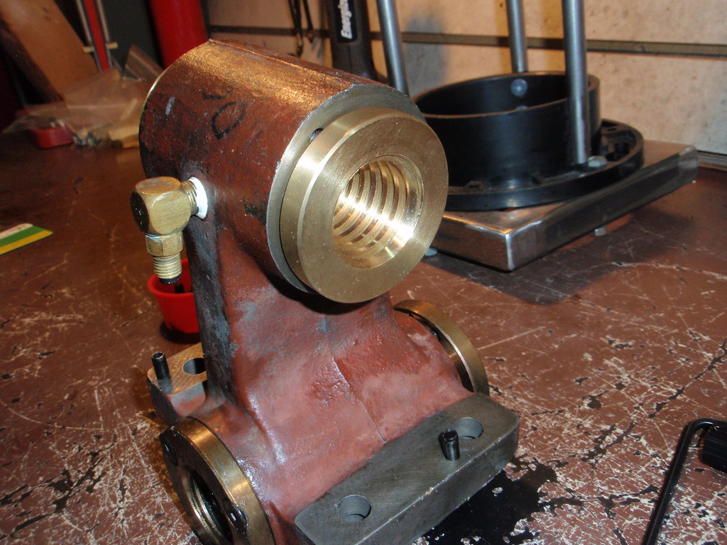
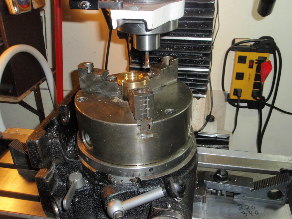
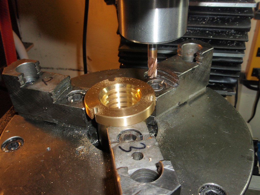
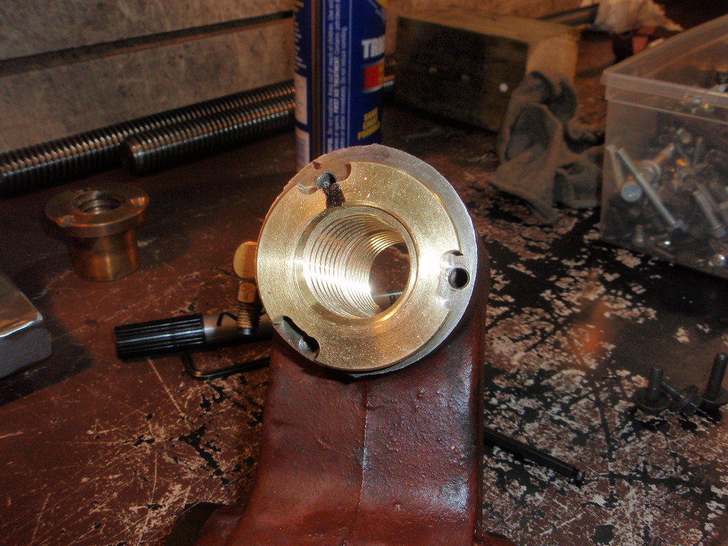
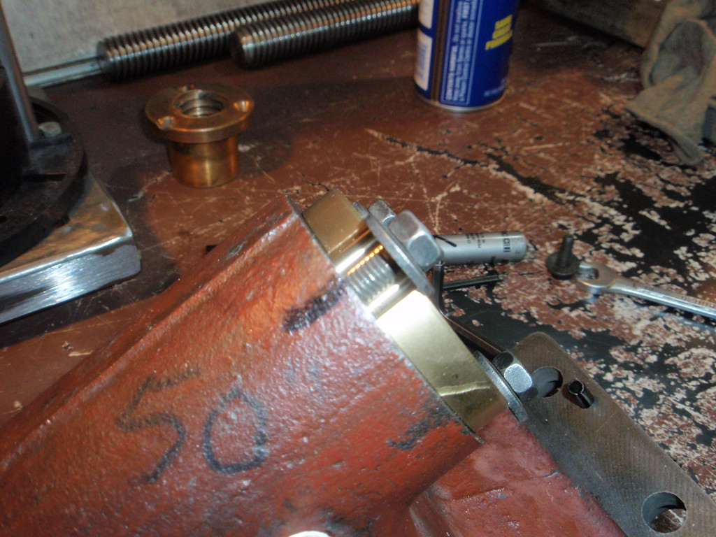
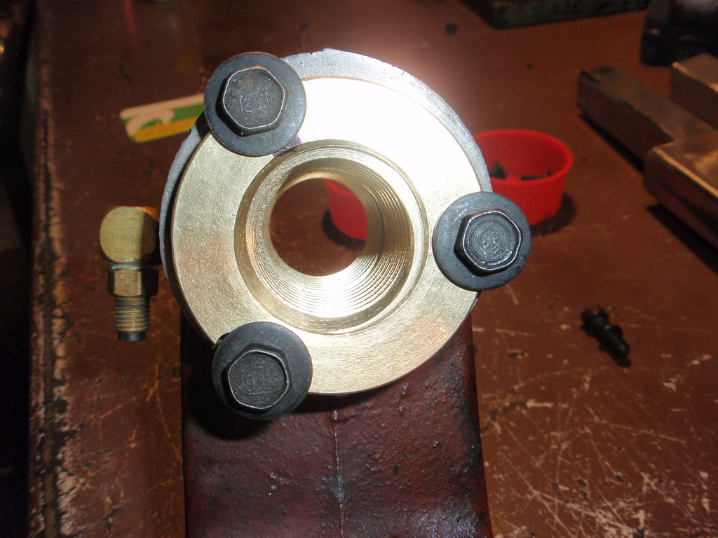
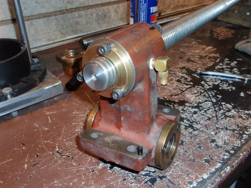
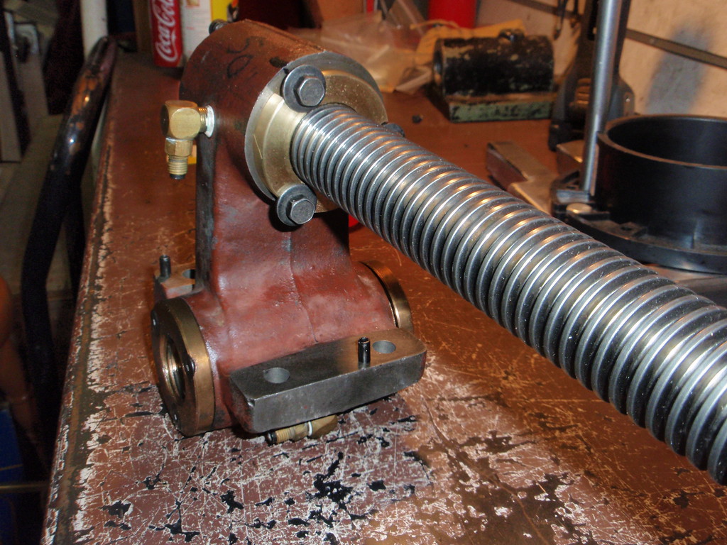
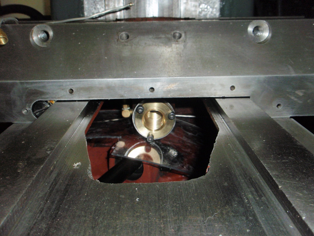
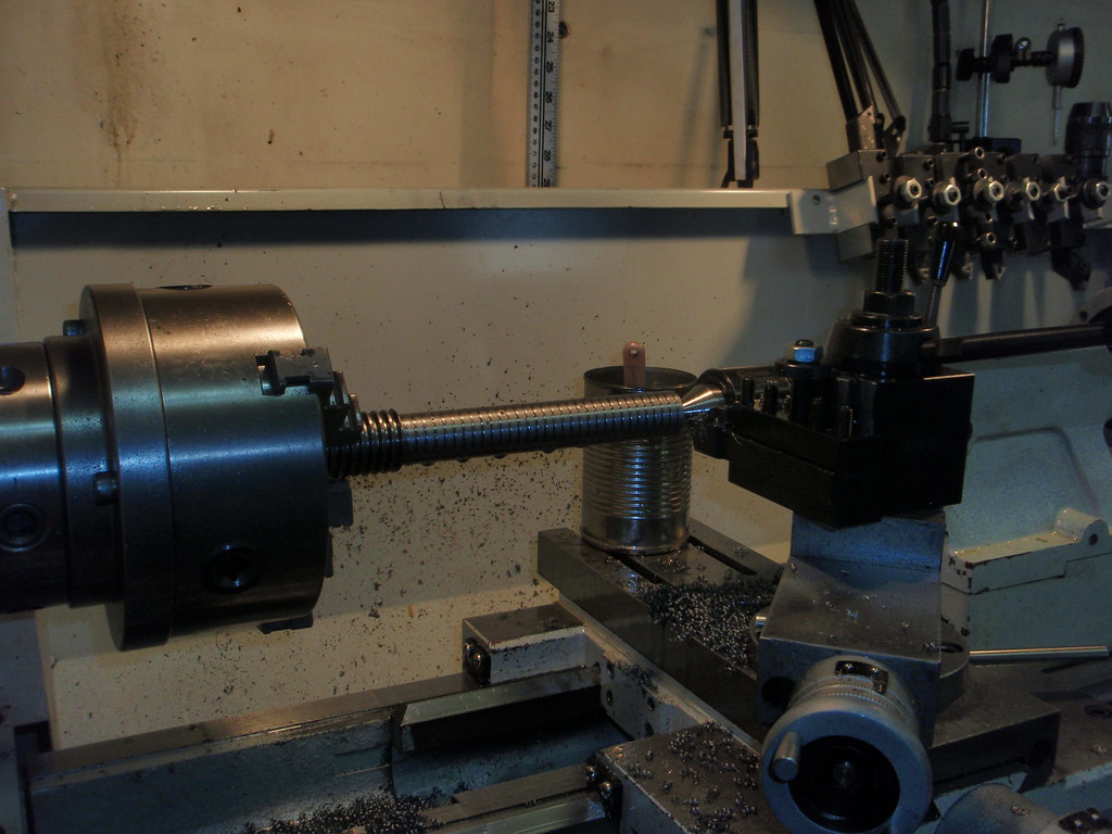
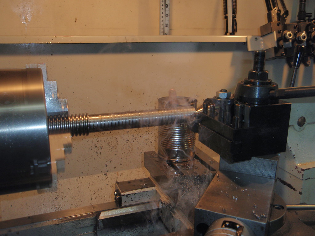
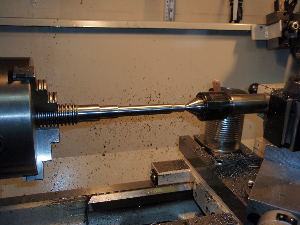
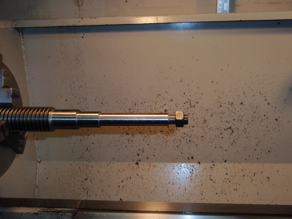
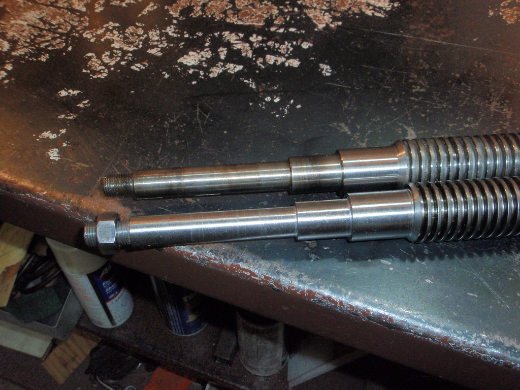
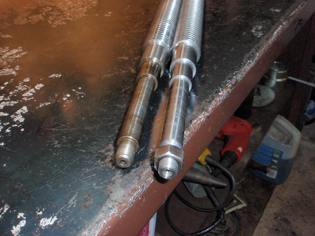
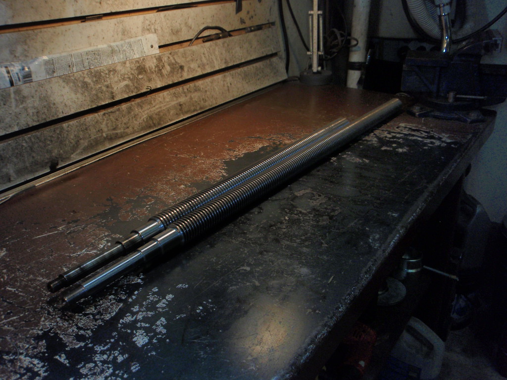
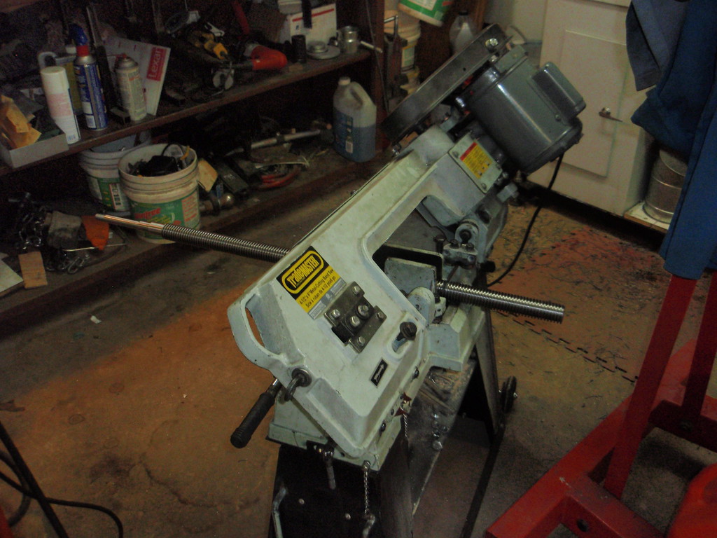
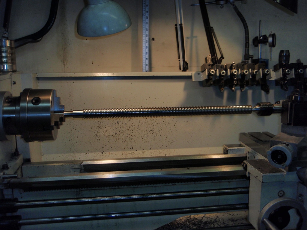
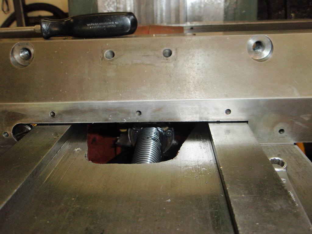
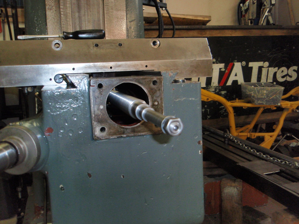
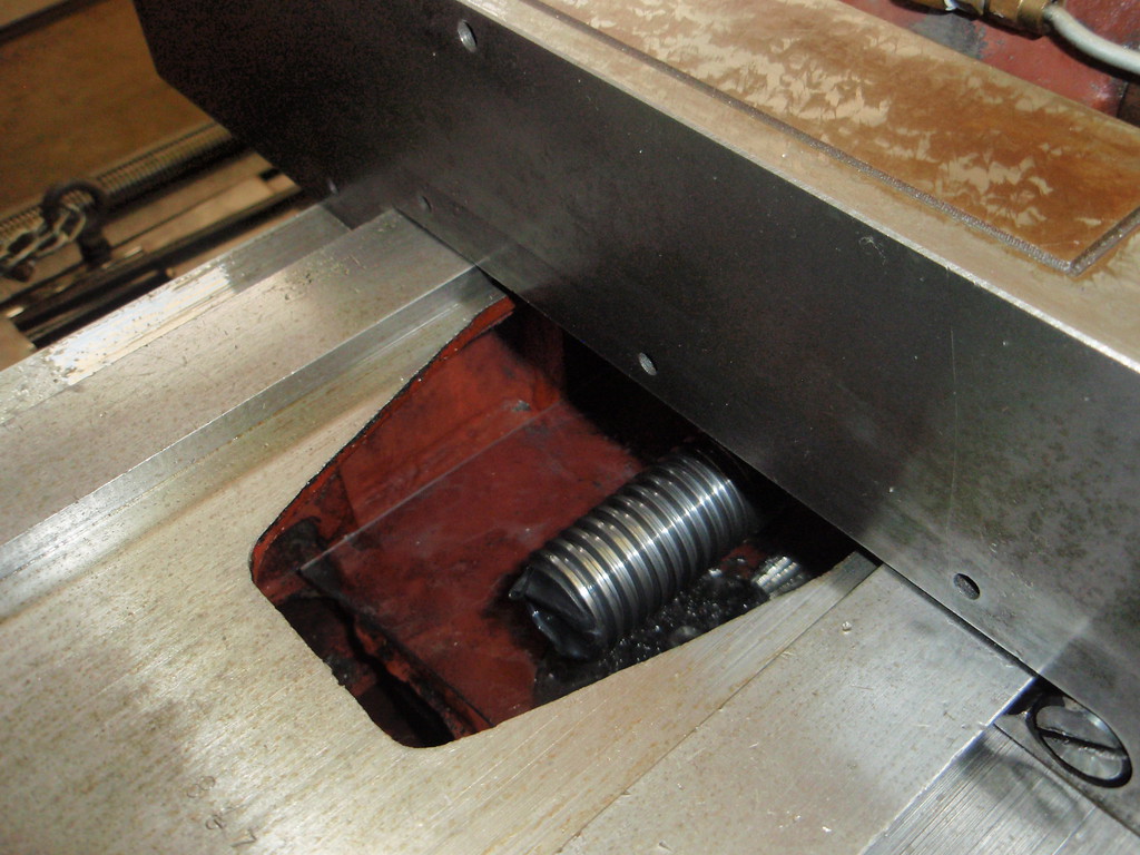
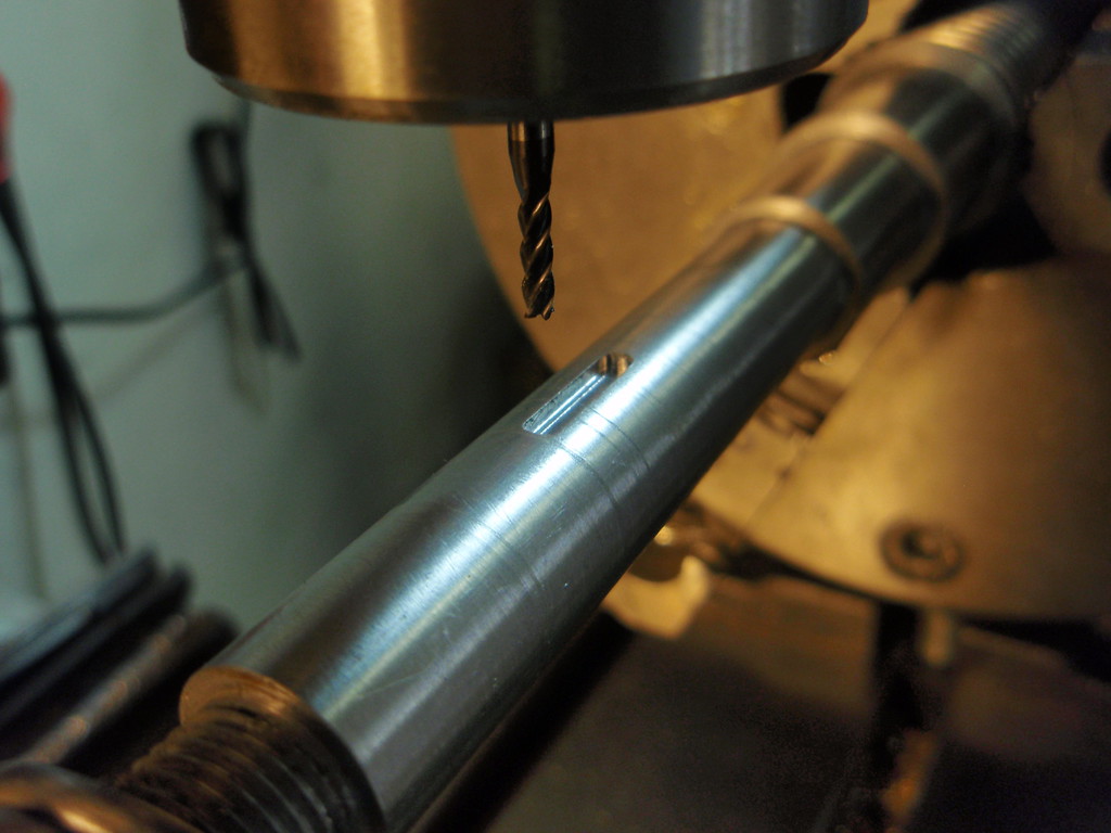
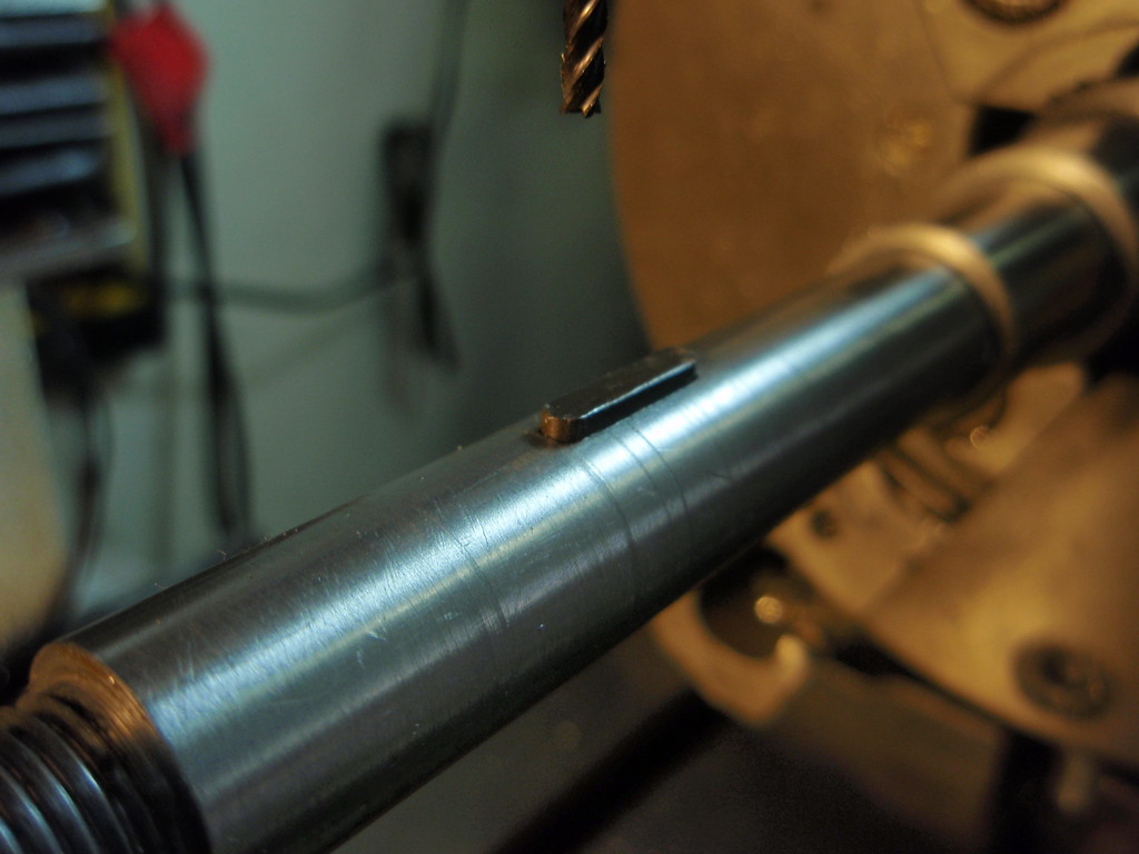
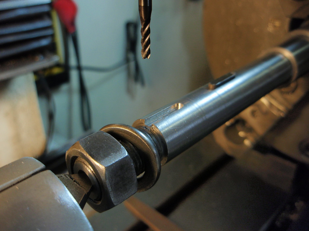
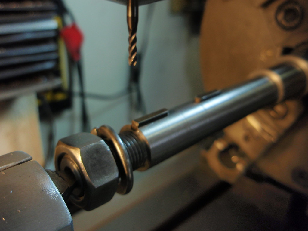
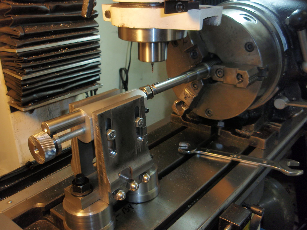
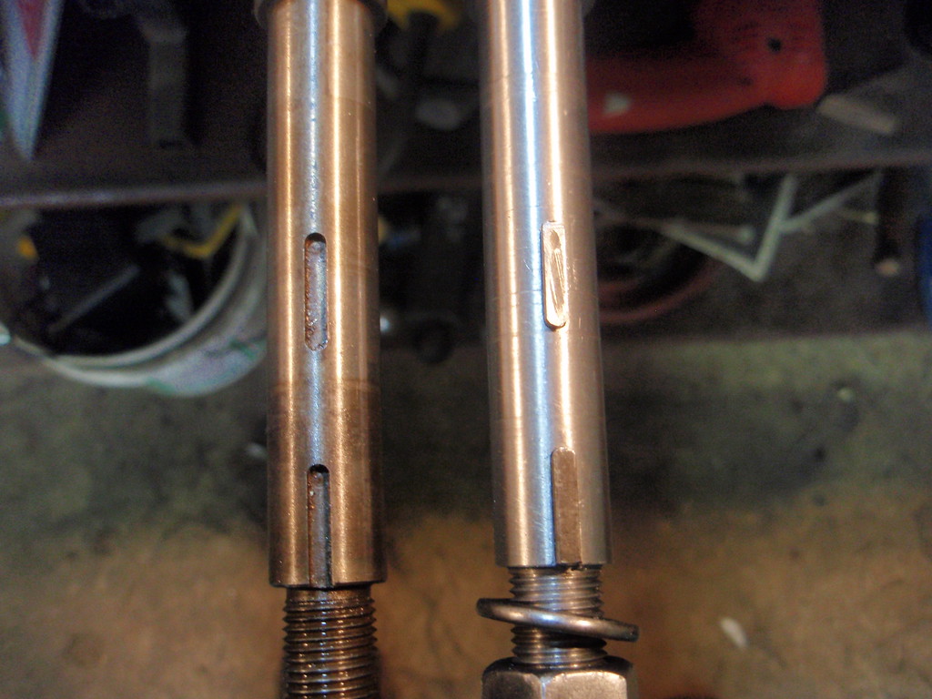
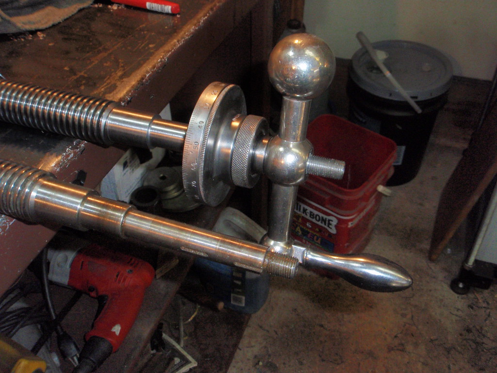
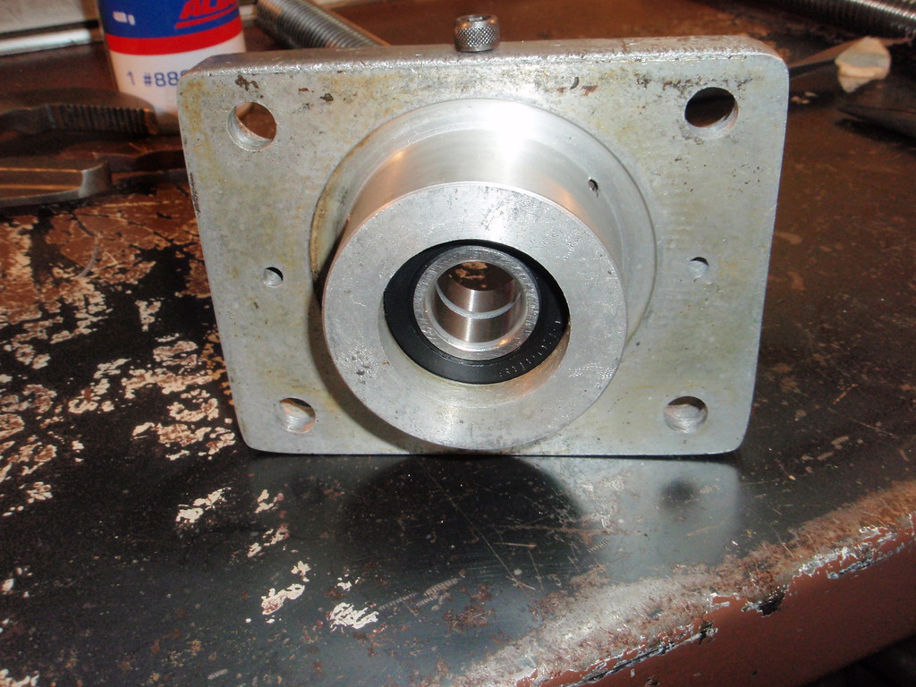
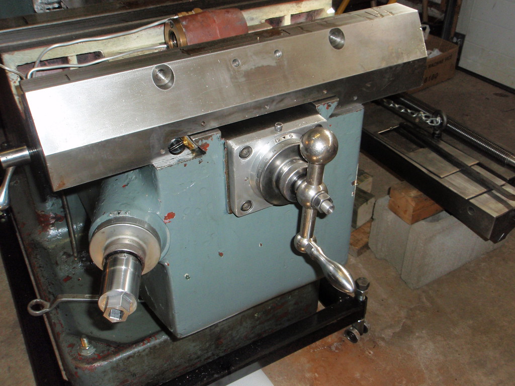
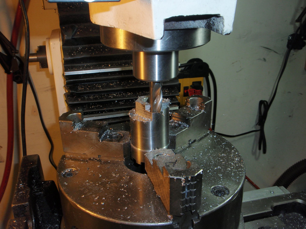
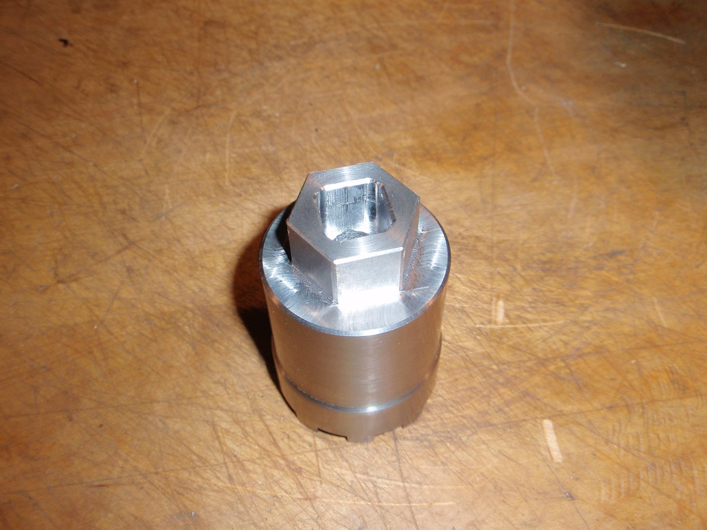
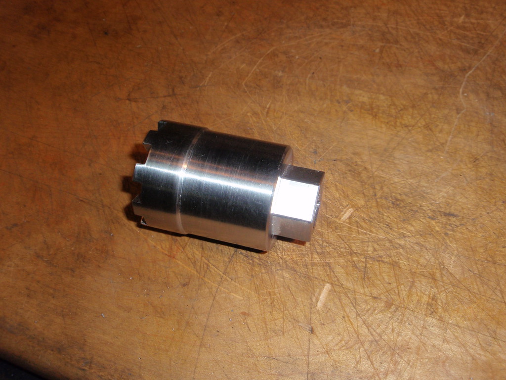
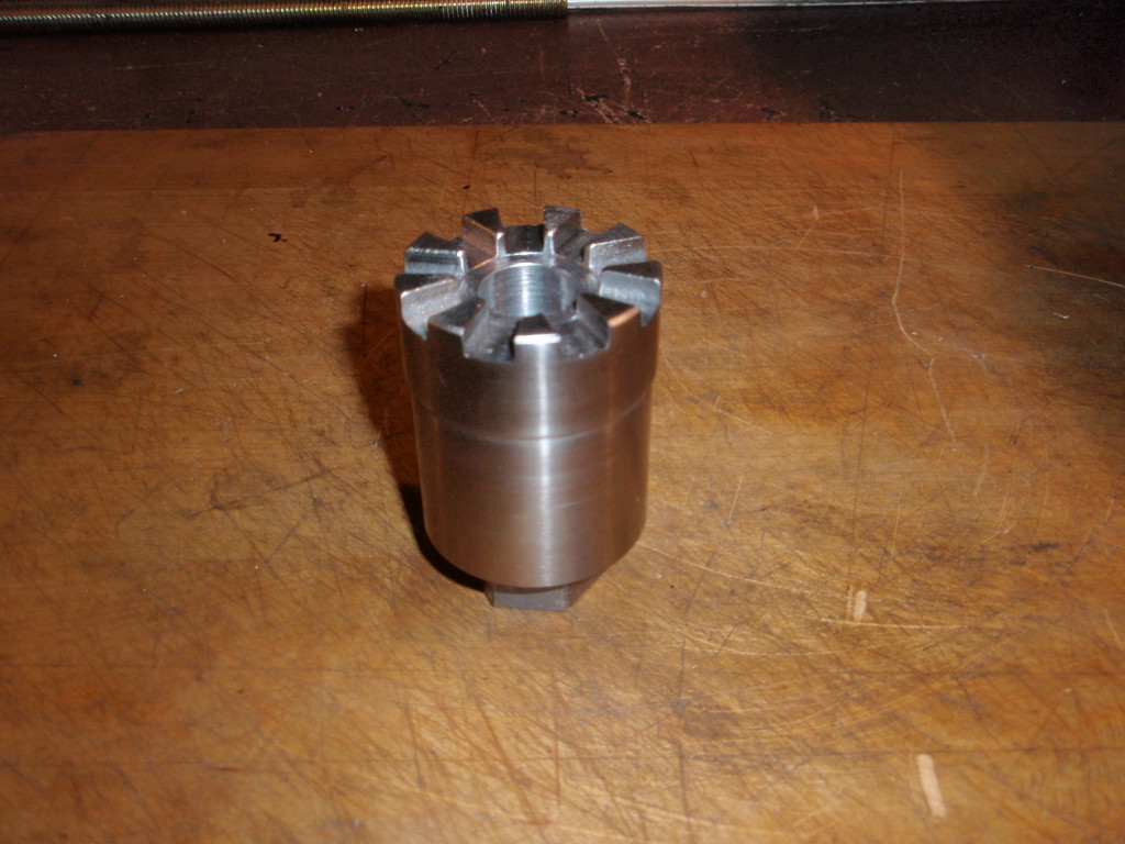
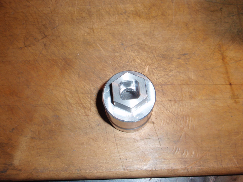
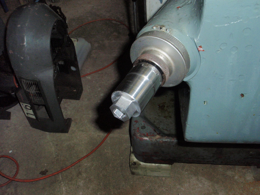
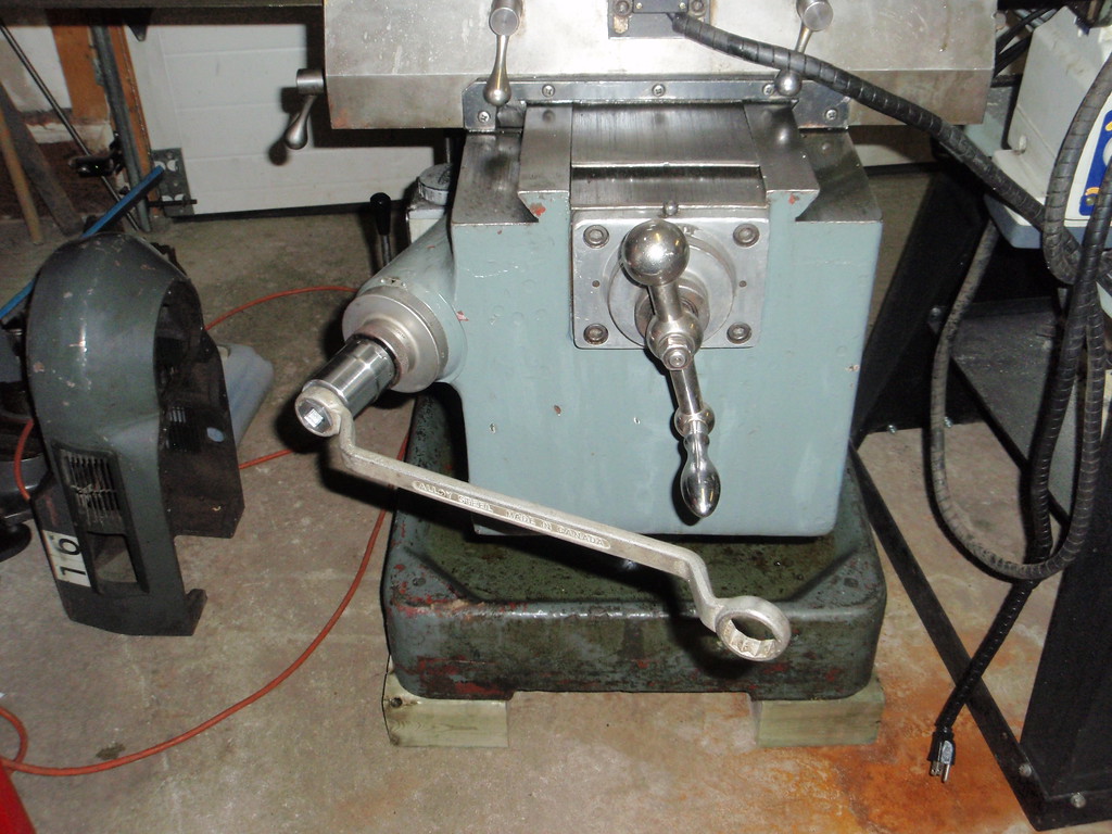
It was in a pretty neglected state so a complete teardown ofthe table, cross-slide and knee was required. There was no crank handle for theknee so I made up this 9 spline adapter that can be turned with a 15/16” wrenchor a ½” square drive on a drill.


John Conroy

member
Premium Member
I wanted it to be easily moveable so I welded up a base using 2” square tubing with ¼” wall. I welded ¾” nuts on the corners to mount wheels.


I made it in 2 pieces to make it easy to install without having to remove the wood blocks the machine was sitting on. I used 9/16”threaded rod to bolt the machine to the base. I had to make some tapered spacers to match the angle of the rounded top of the machine’s bolt holes.


John Conroy

member
Premium Member


I tried using the same wheels I use to move my lathe and thePM932 mill but they proved to be not strong enough, the bearing outer races split due to the weight of the machine. It weighs about twice as much as the other machines. Even after I machined some steel tires to protect the outer races. I came up with a solution for this which I will detail later. The ball bearing wheels lasted long enough to get it into a good working position.


John Conroy

member
Premium Member


Since the motor is 3 phase I bought a cheap Chinese Hyanyang VFD to convert the 240 volt single phase power in my garage to 220 volt 3phase. I completely gutted the electrical box on the machine and went to work using the crappy instructions that came with the VFD as well as a lot of research done on the internet. I mounted the existing electrical box on a swingarm and re-enforced the bottom sheet metal with a piece of ¼” by 2” steel.


I removed the digital display from the VFD and mounted it in the door of the box and used 2 latching switches, 1 momentary switch and a 10,000 ohm linear potentiometer to provide the functions I wanted. It has 1 switch for ON/OFF, another for FORWARD/REVERSE the momentary switch is for JOG and the pot is for the variable speed. I kept the maximum frequency for the motor to 60HZ as the mill has a variable speed head. It wound up looking like this when I was done with it and it works great.


John Conroy

member
Premium Member


If you are familiar with VFD set up, here are the settings Iused. I chose not to run the motor at more than 60hz.


Next I moved on to the table, cross-slide and knee. I used my engine crane to remove these heavy parts and found that the bevel drive to lift the knee was completely full of chips. I still can’t believe it worked like this, and pretty smoothly too!


Here are some pics of the process I used to remove the knee.


John Conroy

member
Premium Member


I used engine shampoo and a pressure washer to clean out all the mess inside the knee.


All the parts were in good shape with only cleaning and new bearings for the bevel drive shaft required. I cleaned out and re-used the bearing on top of the knee jack and installed a plexiglass shield to keep the chips off the bevel drive area in the future. I reinstalled the knee and adjusted the gib. I used lots of high pressure moly-grease on the bevel drive gears.


John Conroy

member
Premium Member
The Y axis lead screw and bronze nuts were completely worn out. I found out later that many Taiwanese mills use this same weird size threaded shaft for the screw. It is 32mm diameter but has 5 TPI acme threads, not the metric trapezoidal thread you would expect on metric sized shaft. The nuts are available for a reasonable price but not the screw. I wound up buying a 3 foot length of 1.25” acme threaded shaft locally and ordering 2 left hand thread nuts from Roton Industries, who were, by the way, great to deal with. The nuts were not the correct dimensions on the OD but were the correct 1.25”left hand acme thread to fit the shaft I bought. Since 32mm = 1.259” this seemed a good way to convert the shaft to a standard size. When the new nuts came I machined them to fit the mill’s feed nut bracket. I then machined the new screw shaft to match the original shaft’s dimensions and milled the keyway slots. I bought new RH thread 32mm nuts for the X axis from Supra Machine Tools on eBay. They were nearly a straight drop in part with only the bolt holes pacing needing to be modified.


PeterT

Ultra Member
Premium Member
Wow John. When you see the pics laid out in start to finish manner, its evident how much TLC effort you put into the mill. And now you have an awesome machine. Thanks for posting.

Re the legacy chips buildup over the lead screw / nut area, did you get the impression there was supposed to be some sort of cover that was missing. Or maybe a certain job setup where they migrated down? Could a guy even have a peekaboo in there once in a while by retracting the table & removing a cover, or does it require a more extensive table removal like the point you were at?
 

John Conroy

member
Premium Member
There is a kind of layered cover over the bevel gears you can see in the last pic. I guess some chips get by it and over 30 years of use with no maintenance they build up. You can look up into that area from underneath the knee with a mirror or by removing the knee lead screw. When I had the leadscrew out to intstall the power feed there were no chips there so my plexiglass shield is working as I've been using the mill for 3 years like that.
 
Top