-
Scam Alert. Members are reminded to NOT send money to buy anything. Don't buy things remote and have it shipped - go get it yourself, pay in person, and take your equipment with you. Scammers have burned people on this forum. Urgency, secrecy, excuses, selling for friend, newish members, FUD, are RED FLAGS. A video conference call is not adequate assurance. Face to face interactions are required. Please report suspicions to the forum admins. Stay Safe - anyone can get scammed.
-
Several Regions have held meetups already, but others are being planned or are evaluating the interest. The Calgary Area Meetup is set for Saturday July 12th at 10am. The signup thread is here! Arbutus has also explored interest in a Fraser Valley meetup but it seems members either missed his thread or had other plans. Let him know if you are interested in a meetup later in the year by posting here! Slowpoke is trying to pull together an Ottawa area meetup later this summer. No date has been selected yet, so let him know if you are interested here! We are not aware of any other meetups being planned this year. If you are interested in doing something in your area, let everyone know and make it happen! Meetups are a great way to make new machining friends and get hands on help in your area. Don’t be shy, sign up and come, or plan your own meetup!
You are using an out of date browser. It may not display this or other websites correctly.
You should upgrade or use an alternative browser.
You should upgrade or use an alternative browser.
Electrical help.
- Thread starter jorogi
- Start date
@jorogi I think it may have been this one but there is a lot missing. Post 229 and 230 explain why stuff is missing.
In the first picture there are three contactors , KM1 , KM2 & KA . When you power up the lathe , by plugging it in , KA becomes energized , the transformer and the 24 volt control circuits are also energized , KA gives a solid click . When I say power up , I mean plug in the machine or turn on the breaker , my garage only has the one 220 volt outlet so whatever machine I'm using gets plugged in at that time , the lathe , the knee mill or the welder. There isn't a master power switch on the front control panel , just an emergency stop , a jog button and a power on lamp .
I'm not happy...
I'm not happy...
BaitMaster
Ultra Member
Is it an inverter Tig or a transformer based tig?
Thanks all, I feel confidence knowing the CHMWM braintrust is here to help.
The welder in question is an Everlast 255xt, TIG and stick machine, about eight years old. An inverter machine which I have been happy with for the most part. The torch is a CK Worldwide water cooled unit.
The stick function works fine and the lack of TIG has really uped my stick abilities. Really up but from a pretty low point to start with.
I don't want to be that guy that tells the expert what the problem is but........my suspicion is the potentiometer in the foot pedal.
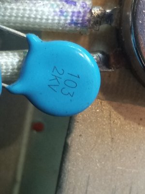
Last time I tried to TIG was probably last October or November. I had a tiny arc (start arc ?) but it would not strike a welding arc. Argon flow was fine. I contacted Mike at Everlast and we went through several things and came to him sending me a Everlast video on YouTube testing a 10ohm foot pedal. I ran through the tests and reported back to Mike. He couldn't really make sense of what I had found and I got the sense that he was following a troubleshooting flow chart and was not himself technically savvy. Not knocking the guy. Anyway this led to more videos that were down in the guts of the pc boards, frankly a little intimidating and I was really very busy at the time. I'm now at a point where I need my TIG. I'm going to post and then follow up with test results in the next post, first the potentiometer and second is the doohickies between the legs of the potentiometer (capacitors ?)
The welder in question is an Everlast 255xt, TIG and stick machine, about eight years old. An inverter machine which I have been happy with for the most part. The torch is a CK Worldwide water cooled unit.
The stick function works fine and the lack of TIG has really uped my stick abilities. Really up but from a pretty low point to start with.
I don't want to be that guy that tells the expert what the problem is but........my suspicion is the potentiometer in the foot pedal.
Last time I tried to TIG was probably last October or November. I had a tiny arc (start arc ?) but it would not strike a welding arc. Argon flow was fine. I contacted Mike at Everlast and we went through several things and came to him sending me a Everlast video on YouTube testing a 10ohm foot pedal. I ran through the tests and reported back to Mike. He couldn't really make sense of what I had found and I got the sense that he was following a troubleshooting flow chart and was not himself technically savvy. Not knocking the guy. Anyway this led to more videos that were down in the guts of the pc boards, frankly a little intimidating and I was really very busy at the time. I'm now at a point where I need my TIG. I'm going to post and then follow up with test results in the next post, first the potentiometer and second is the doohickies between the legs of the potentiometer (capacitors ?)
Attachments
So the test in the video is as follow.
Read the resistance between pins
4-3
5-4
5-3
With thier pedal their readings were
0
9.5
9.5
with no pedal application and
9.5
0
9.5
with full pedal application.
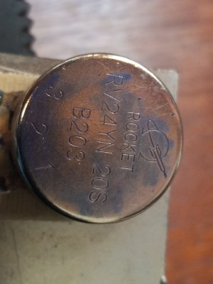
I suspect that my pedal is not a 10ohm pedal but I'm not sure if it's a 22 or 48 (+-).
So with no pedal I get
.9 k ohm
19.5
19.5
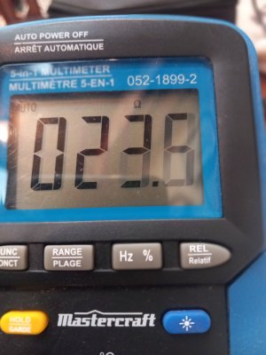
and with full pedal
19.7 k ohm
23 ohm
19.5
I'm suspicious of the middle full pedal reading as it doesn't fit the pattern of thier test and it was not a stable reading and was in the ohm range.
A couple of pics
Read the resistance between pins
4-3
5-4
5-3
With thier pedal their readings were
0
9.5
9.5
with no pedal application and
9.5
0
9.5
with full pedal application.
I suspect that my pedal is not a 10ohm pedal but I'm not sure if it's a 22 or 48 (+-).
So with no pedal I get
.9 k ohm
19.5
19.5
and with full pedal
19.7 k ohm
23 ohm
19.5
I'm suspicious of the middle full pedal reading as it doesn't fit the pattern of thier test and it was not a stable reading and was in the ohm range.
A couple of pics
Attachments

slow-poke
Ultra Member
B203 is a 20k pot.
So with the pot disconnected from the circuit board:
1) It should measure close to 20k across the outside terminals
2) with the meter connected to the 2 & 3 terminals, the resistance should be close to 0 Ohms with the pot turned fully clockwise and 20k when turned fully CCW. And the value should be a linear value in between, with no dropouts.
3) With the meter connected to the 1 & 2 terminals, the resistance should be close to 0 Ohms with the pot turned fully CCW and 20k when turned fully clockwise. And the value should be a linear value in between.
If the pot measures as described, the pot is not the problem.
If the pot is some distance from the board (connected via a cable?), you can test at the far end of the cable (circuit board end but still disconnected) and wiggle the cable at any points that are likely to be possibly intermittent for example where the cable exits the enclosure. If the ohmic values are consistent when wiggling the cable you can probably rule out the cable as well.
Link to the videos would be helpful.
Video link.
My tests were as shown in the vid at the cable ends. IIRC I did continuity tests on each conductor in the cable.
I had guessed that I had a 20k potentiometer from the 19.5k readings I was seeing. What you're saying seems to be is that the wobbly 23 ohm reading I'm seeing is not good.
I had guessed that I had a 20k potentiometer from the 19.5k readings I was seeing. What you're saying seems to be is that the wobbly 23 ohm reading I'm seeing is not good.
Last edited:
in my experience, almost all foot pedal issues relate to the cable and/or connection, the pedal gets kicked around a lot and often where the cable goes into the foot pedal there is a broken or disconnected wire
have you tried to run the tig in lift arc without the pedal
the value of the pot inside the foot pedal doesnt make much difference, its used as a voltage divider in the inverter machines, you can sub a 10k, 20k, 30k pot in there and it will still function, there is normally also a microswitch inside the pedal that some times fails, but again its almost always the cable
when i did time in a tig shop at least 1 pedal every month had problems (about 20 machines), 99% of the time it was cable related
slow-poke
Ultra Member
23 Ohms is probably fine as long as it's not flashing to open.Video link.
My tests were as shown in the vid at the cable ends. IIRC I did continuity tests on each conductor in the cable.
I had guessed that I had a 20k potentiometer from the 19.5k readings I was seeing. What you're saying seems to be is that the wobbly 23 ohm reading I'm seeing is not good.
23/20000=0.001, so that's close enough to zero.
So if the microswitch and pot, pass the cable wiggle test, the problem is elsewhere.
Can you post the other other troubleshooting videos?
BaitMaster
Ultra Member
The connectors for the cables are usually pin and socket. The “sockets” usually “spring” when the pin is inserted. That “springiness” gets worn out over time and the sockets end up permanently loose and cause intermittent issues. Very common.
Ah, I should have paid more attention to good old Dad (an electronics engineer, but definitely not a teacher). I can't find the scary vids (yet) but I came across this one which seems like a good next step.23 Ohms is probably fine as long as it's not flashing to open.
23/20000=0.001, so that's close enough to zero.
So if the microswitch and pot, pass the cable wiggle test, the problem is elsewhere.
Can you post the other other troubleshooting videos?
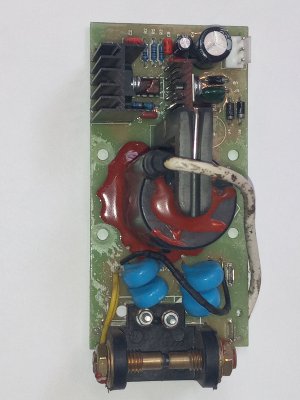
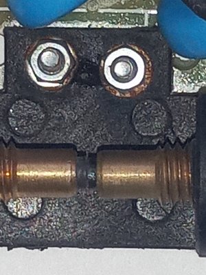
So I started to run the test and adjustment in the above video. No arc across the contacts but there was a tiny spark between the two Phillips head screws and nuts, beside the contacts and holding the contact holder to the pc board. It might not show up in the picture but it looks like there is a carbon trace between the two. Not sure where the power is coming from.
So plan of action.
Go up to my cousins cabin and drink beer.
Tomorrow, check for replies telling me I'm an idiot and to do it this way. Go out to the shop and not be an idiot, or failing a lack of comments,
Go out to the shop and remove the screws, clean everything with isopropyl alcohol, reassemble and test.
Would a judicious slathering of RTV silicone help or just hide the problem ?
Attachments
If you'd like a second set of eyes give me a call. I've done a fair amount of circuit board work in the past, not promising anything but no harm in trying.
A good contact cleaning may be all that's required. One piece of equipment I used to work on needed to be shut down every 3 months and every circuit board removed and the contacts cleaned or weird unexplainable faults started to show up.
Enjoy your beer!
A good contact cleaning may be all that's required. One piece of equipment I used to work on needed to be shut down every 3 months and every circuit board removed and the contacts cleaned or weird unexplainable faults started to show up.
Enjoy your beer!
I would really love someone to start making cheap and identical copies of the Miller wireless pedal, because the second hand one I have has been flawless.in my experience, almost all foot pedal issues relate to the cable and/or connection, the pedal gets kicked around a lot and often where the cable goes into the foot pedal there is a broken or disconnected wire
have you tried to run the tig in lift arc without the pedal
the value of the pot inside the foot pedal doesnt make much difference, its used as a voltage divider in the inverter machines, you can sub a 10k, 20k, 30k pot in there and it will still function, there is normally also a microswitch inside the pedal that some times fails, but again its almost always the cable
when i did time in a tig shop at least 1 pedal every month had problems (about 20 machines), 99% of the time it was cable related
slow-poke
Ultra Member
Not sure that's a good idea, I'm guessing those bolts need to make contact with those traces, looks like they are the current path to the contacts.It looks like the heads of the two screws are touching the edge of two traces on the circuit board. Once the board is cleaned putting insulating washers under them might help.
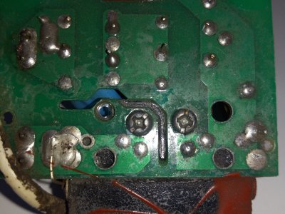
I'm trying to make sense of the xx310 image. It looks like they are using a wire, possibly soldered to a trace below it for added current capability, but it's not obvious what it connects to near the screws?
What resistance do you measure access those two screws?
Last edited: