• Scam Alert. Members are reminded to NOT send money to buy anything. Don't buy things remote and have it shipped - go get it yourself, pay in person, and take your equipment with you. Scammers have burned people on this forum. Urgency, secrecy, excuses, selling for friend, newish members, FUD, are RED FLAGS. A video conference call is not adequate assurance. Face to face interactions are required. Please report suspicions to the forum admins. Stay Safe - anyone can get scammed.

DRO install on Myford ML7R

Xyphota

Ultra Member
I purchased a DRO from Aikron as it was mentioned in another thread and am working on installing it. I am about halfway through installing the longitudinal scale. I have the scale and shield mounted and am milling up a few brackets to fix the reader head to the backside of the carriage.

WhatsApp Image 2022-10-05 at 11.43.07 PM.jpeg

Before the milling the next part on the bracket, I wanted to drill and tap a few holes on the carriage and then match those features. There is not a lot of material on the Myford carriage so I decided to drill the holes in the mill to keep the drill bit from wondering and blowing out the side of the carriage. I knew holding the carriage in the mill in the orientation I needed was not going to be straight forward. I wanted to use the t-slot on the front side of my table and clamp the carriage vertically on that face. Unfortunately the previous owner of my mill mounted the mill's DRO on that side of the table, so I had to spend a few hours relocating it to the back of the table.

WhatsApp Image 2022-10-05 at 11.43.08 PM.jpeg

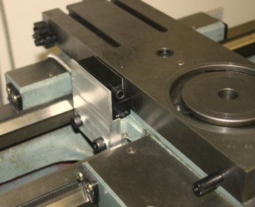
The next minor hurdle was that the front t-slot is smaller than the table t-slots as it is presumably only really meant to be used to hold travel stops for power-feed setups (Except the t-slot seems a bit overkill for this LOL). I milled some flats into the threaded section of some 1/2" bolts, as the bolt heads fit inside the t-slot portion quite nicely, and the remaining threaded portion of the bolt would work with the rest of my clamping hardware.

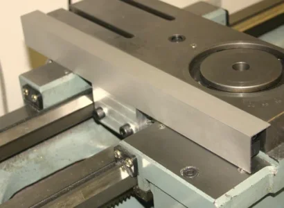
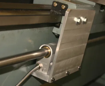
From here it was tricky to hold everything in place as it was clamped down, two extra hands would have made it much easier. The aluminum flat bar clamped to the table was used to support and align the carriage. I was also *just* inside the workspace that the mill head could reach by moving the ram out all the way. If the carriage was an inch longer I dont think I would have been able to reach the far edge.

WhatsApp Image 2022-10-05 at 11.43.08 PM (1).jpegWhatsApp Image 2022-10-05 at 11.59.09 PM.jpeg

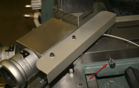
From here the carriage was tapped around a bit with a mallet to get it true and then drilling the holes was straight-forward.

WhatsApp Image 2022-10-05 at 11.43.09 PM.jpeg

Next steps are to re-install the carriage and finish the brackets for the longitudinal axis scale.
 
Got a bit more work done over the last two days. I installed the reader head for the cross-slide which just required a simple bracket.
MicrosoftTeams-image (10).jpg

The scale for this axis will be a magnetic strip which will be embedded into the underside of the cross-slide, as inspired by the DRO kit sold my MachineDRO in the UK. This embedded track needs to be extended however so a wing was machined and bolted onto the backside of the cross slide.

MicrosoftTeams-image (11).jpgMicrosoftTeams-image (12).jpg

I also got the display mounted. I drilled and tapped some holes in to the casting that supports the pulleys. I'm hoping that there isnt too much vibration that would otherwise cause the display to vibrate out of position, so we will see.

MicrosoftTeams-image (13).jpg

All that is left is to mill the slot for the magnetic strip, mount the strip and reassemble, and then tidy up all the cables.
 
They came that way from the factory! They are for oil. I think they are technically not zerk fittings but close enough. You use one of those push-oiler things to feed them.
 
They came that way from the factory! They are for oil. I think they are technically not zerk fittings but close enough. You use one of those push-oiler things to feed them.

Did the push-oiler come with the machine. Post an image of the oiler please.
 
All that is left is to mill the slot for the magnetic strip, mount the strip and reassemble, and then tidy up all the cables.
Following with great interest!

Please continue with the detailed pictures! I have a Super 7 and have been mulling over how to mount scales for both axes. I haven't seen the cross slide bottom approach before so it's particularly interesting. Is the scale "just" a stick on tape or is it packaged?

I'm waffling on the other scale mounting because I have the taper turning attachment mounted and the/your logical approach would compete for space.

D:cool:
 
The scale is a magnetic tape that is stuck on in two layers.

This is the kit I'm stealing inspiration from:

The reason I went with Aikron DRO is it was slightly cheaper and the display has a data output option. The data output option was important to me because I would like to install a constant SFM controller (arduino) when I install a VFD in the next couple months.

I think there are some model engineer forums that discuss various DRO options to be compatible with the taper turning attachment, including mounting a magnetic tape without a shield behind the apron on the operator side.
 
Last edited:
without a shield behind the apron on the operator side.

This whole install is really slick. In particular, I love how you made the scale on the compound internal.

I have not ordered a DRO for my lathe yet. Partly because I'm not convinced of the value yet. I've used a lathe and dials for close to 50 years and never wanted a Readout until I put one on my mill. But I feel like they are very different animals when it comes to the value of a DRO. But the thing that has stopped me cold is the way the scales get in the way. Particularly the cross-slide. I don't like it on the working side because of all the chips and I don't like it on the tailstock side because it interferes with bumping the tailstock for continuing an operation. Your approach dissolves both of those concerns.

I can see the read head cable for your cross slide, but where and how is the read head itself mounted?
 
I have not ordered a DRO for my lathe yet. Partly because I'm not convinced of the value yet. I've used a lathe and dials for close to 50 years and never wanted a Readout until I put one on my mill. But I feel like they are very different animals when it comes to the value of a DRO. But the thing that has stopped me cold is the way the scales get in the way. Particularly the cross-slide. I don't like it on the working side because of all the chips and I don't like it on the tailstock side because it interferes with bumping the tailstock for continuing an operation.

IMO a DRO is just as useful & important on a lathe as a mill. Its an accurate measuring device, who wouldn't want accurate measuring capability, especially when DRO installations are a fraction of the cost they used to be? There is nothing wrong with old school dials & gages but DRO makes machining so much easier & enjoyable. Just bite the bullet. You can spend the next 50 years pondering why you waited so long LOL.

I had similar thoughts about the cross slide positioning so it may vary by individual & lathe. My table lock is on RHS & that is important to me so I installed scale on LHS with angle aluminum shield that fits flush. No swarf or fluid issues or damage over the years, knock on wood. I do give up the travelling steady, in fact I used the bolt holes for the DRO mount plate. But I rarely use steady in my own work & have plans for a better table mount version (project #107). The bed axis DRO scale is a no brainer. I also installed a compound scale at the time but in hindsight that rarely got used so I've since removed it. Newall is a bit more compact but there are many offshore scales that have comparably compact footprints & cross sections, just choose wisely.

Sorry, I don't really understand the need to bump a tailstock. But I am admittedly anal retentive about anything that can adversely affect wear & tear on lead screws, sliding surfaces etc. but each to their own.
 

Attachments

  • J500x366-04721.webp
    J500x366-04721.webp
    19.4 KB · Views: 14
  • J500x406-01124.jpg
    J500x406-01124.jpg
    30.5 KB · Views: 14
  • J499x316-02505.webp
    J499x316-02505.webp
    17.1 KB · Views: 14
  • J500x409-03302.webp
    J500x409-03302.webp
    17.5 KB · Views: 14
Yeah the main reasons I went with this method is because I’m sure if I mounted it on the chuck side I’d eventually run the chuck into it, and mounting it on the back side would cover the saddle lock.
I can see the read head cable for your cross slide, but where and how is the read head itself mounted?
you can see how it is mounted in the first picture of post #3
 
Last edited:
you can see how it is mounted in the first picture of post #3

I think I get it now. When I saw it in post 3 I had no idea what I was looking at.

So I assume the head points up and reads the mag tape that passes back and forth above it. I also assume that the table extension you made is not installed yet - in fact not even any holes yet for it in that photo. Looks great @Xyphota !
 
Yes haha, in post #3, second photo I’m just holding it in place with my finger, in the third photo I had drilled and tapped the holes to fasten them together.
 
You can spend the next 50 years pondering why you waited so long LOL.

That might well be! I know it sure was a game changer in my mill. I guess I'm just more set in my ways on the lathe. But, you are right. It's prolly just like the mill. But no chance I'll live another 50.

@Xyphota's cross slide method has me thinking.

Sorry, I don't really understand the need to bump a tailstock. But I am admittedly anal retentive about anything that can adversely affect wear & tear on lead screws, sliding surfaces etc. but each to their own.

I do a lot of drilling and reaming. Bumping the tailstock is a good way to avoid a lot of cranking. Think of it a bit like threading. Zero the tailstock, drill whatever length works for you, back off a half turn, pull back the tailstock, clear chips, push the tailstock forward to bump the carriage, crank in a half turn, then drill some more.

When I say bump, I mean just gently touch. And I keep lots of way oil on my ways. I'm no more worried about wearing my ways with the tailstock than with my carriage.

As for easy DRO measurements. Obviously I agree. It's just that I've made or purchased many methods for determining or maintain good accuracy. But ya, a DRO would be easier and probably better.

I'm getting there......
 
One question.

I've seen the magnetic tape sold alone, and I've seen it come with a separate stainless steel tape. When sold with the stainless tape, is that to be a backer, or to go in front to protect the magnetic tape from crap and wear?

I suppose if I buy a meter of tape and only need 150mm I have some spare tape so it doesn't matter too much... but I'd like to know none the less.
 
Back
Top