Do these potentiometer numbers mean anything to anyone?

jcdammeyer

John
Premium Member
So forgive my complete and utter ignorance about pretty much anything electrical but...
In my application of attempting to use a treadmill controller board and motor for the sewing machine I am trying to get a foot controlled apparatus made for the potentiometer....
The treadmill motor original circuitry does not start the motor until about 20-30% crank up of the potentiometer but then once it's rolling it can be cranked down some and continue to run. This is not ideal for my sewing machine application as I don’t want too big of a "dead" spot in the pedal travel to start.
So if I use a 5k pot instead of a 10k will that allow more voltage with less travel and there by result in less foot pedal travel to get the motor rolling?
No. It's inherent in the type of controller used for treadmills. I have a COTS controller I bought years ago to run one of the PA surplus treadmill motors. It exhibited the same behavior.

One method of speed control on more sophisticated systems is to measure the back EMF to determine motor speed.

OK. So what the heck does that mean? Back EMF?

Here's the simple explanation. (But long)

If you spin a DC brushed motor and measure the output voltage you will find the faster you turn the motor the higher the generated voltage. They are after all just generators, just like what were on 1964 MGB's for example.

Now ask yourself why a motor turns faster if you apply 12V instead of 6V? Why does it go faster? Especially if there isn't any load on it? (Other than bushing and brush friction). As the motor turns the brushes make contact with new parts of the commutator but the motor is also a generator at the same time inducing voltage in that new winding now connected under the brushes. If that generated voltage (6V) matches the applied voltage (6V) then no current flows through the winding until the motor slows down a tad.

If you apply 12V now there's an extra 6V available to push current into that winding to make the motor spin and spin faster it does. Until the generated voltage equals 12V and we're back to max speed status quo.

Follow so far?

Now there's this thing called static friction and kinetic friction. Initially a voltage like 3V may not be enough to get a 12V motor turning because of the friction. But once you get it to 4V away goes the motor. The trouble is it's now turning at that speed where the windings generate 4V and that's too fast. But because it has momentum and only kinetic friction you can back the voltage to 2V and it turns slowly. Unless you stall it with a load and then it won't restart until the applied voltage is increased.

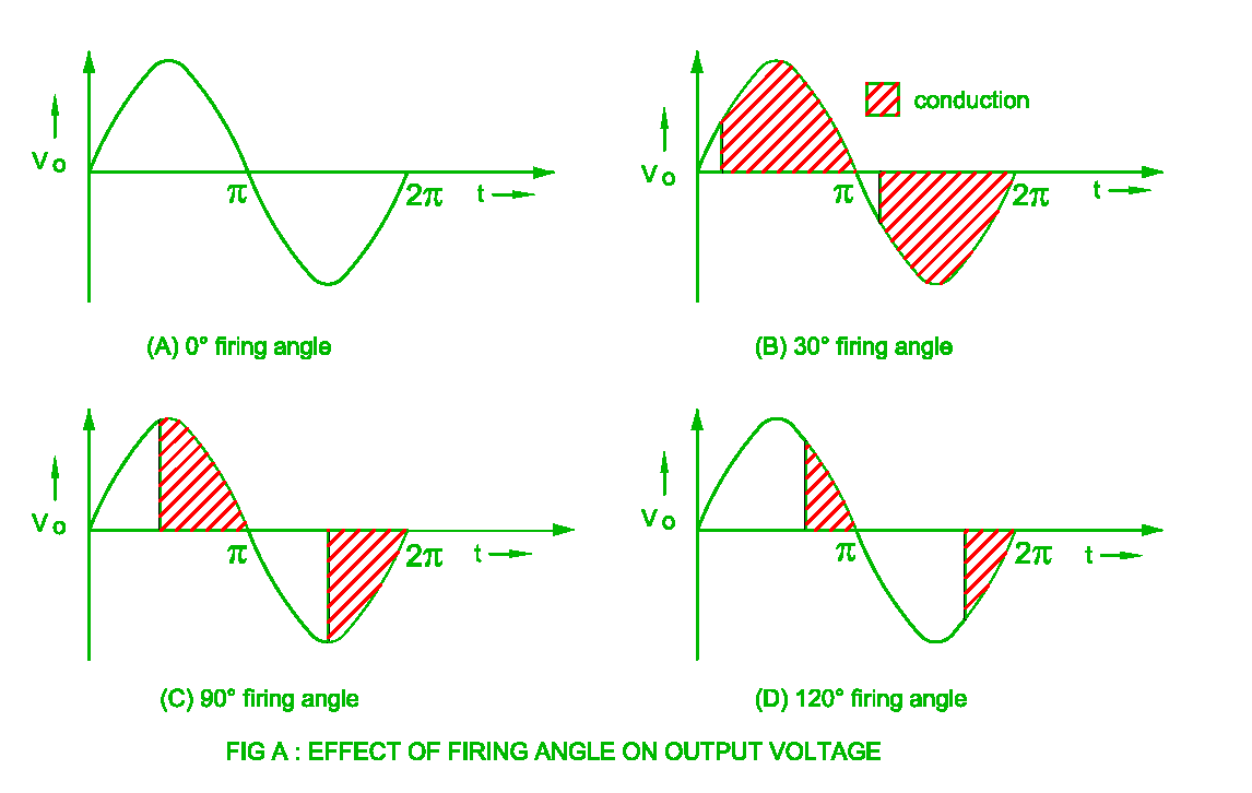
The controllers use something called Pulse Width Modulation (PWM) to vary the speed. They do this by applying the rectified AC (sometimes filtered with a capacitor) to the motor by noting when the AC crosses 0, waiting a certain amount of time and then turning on an SCR or transistor. At the next zero crossing it's switched off and the delay, controlled by that pot is started again. But that delay might mean the SCR isn't switched on until the AC voltage is too low to start it turning. So the pot is turned until the motor starts with the higher AC voltage but now too fast.

Trouble is the voltage is falling near the end of the delay period but the SCR controllers require the zero crossing part of AC to switch off. If it's totally DC filtered at some value then it's just a matter of applying the full voltage for a period of time and then switching it off. Now each time the motor gets a bump of the full voltage and then it's taken away. If the bump is big enough the motor starts to turn and then coasts. Till the next bump.

A combination of the motor winding inductance (number of turns creates inductance) and the power supply capacitor results in a filtered average voltage. So although you are applying say 90V to the motor the average over the PWM period is 3V and the motor turns slowly.

Now remember that generated voltage which is called Back EMF (Electro Motive Force)? Once the controller turns off the 90V for say 95% of the time it can measure what the generated motor voltage is. If it's zero then it increases the PWM to 10% from 5% and again measures during that dead time. At some point we're seeing a voltage as the motor starts to turn. That target voltage is the set point from that speed control pot. When it starts to be more than the set point the PWM is backed off to 5% again or whatever the pot set point is.

So now you can give the motor a huge kick in the pants to start it moving and once it's moving measure the generated voltage and reduce the impact of the kick in the pants until the generated voltage matches the set point. Done right the motor will just accelerate up to whatever speed setting is chosen. May not even over speed.

If it does that's where PID stuff comes in. Or even encoders or resolvers to measure motor position and speed.
 
Last edited:

Susquatch

Ultra Member
Administrator
Moderator
Premium Member
So if I use a 5k pot instead of a 10k will that allow more voltage with less travel and there by result in less foot pedal travel to get the motor rolling?

Basically no. Changing the spec on the pot won't change how it works till it doesn't work at all anymore.
 

jcdammeyer

John
Premium Member
I meant the circles.


Excellent. FWIW, I love it when others explain such things so well.
Didn't do those circles either.

The key thing is SCR devices are cheap, have a low voltage drop so don't get super hot with lots of current. The only down side is the applied voltage has to be close to zero for them to switch off once the the trigger voltage is removed.

You can see in drawing D that when it's switched on the voltage is already pretty low the slow speed for the motor may be more like 170 degree firing angle resulting in an even lower voltage across the motor. But it has to go through zero to turn off. The pot sets the time delay until it's turned on again.

PHASE%2BANGLE%2BCONTROL.png


Of course it's a bit more complicated but that's the general idea. Same reason a cheap lamp dimmer switches on bright and then can be backed off to lower intensity.
 

jcdammeyer

John
Premium Member
So forgive my complete and utter ignorance about pretty much anything electrical but...
In my application of attempting to use a treadmill controller board and motor for the sewing machine I am trying to get a foot controlled apparatus made for the potentiometer....
The treadmill motor original circuitry does not start the motor until about 20-30% crank up of the potentiometer but then once it's rolling it can be cranked down some and continue to run. This is not ideal for my sewing machine application as I don’t want too big of a "dead" spot in the pedal travel to start.
So if I use a 5k pot instead of a 10k will that allow more voltage with less travel and there by result in less foot pedal travel to get the motor rolling?
So hopefully my explanation sheds some light. The cheap $20 far east motor drivers for treadmill motors won't do what you want for your sewing machine. You have to look at something like this instead.
And you will spend between $100US and $400US for it.

There are all sorts of options. But the above link is the type of controller you are looking for.
 

jcdammeyer

John
Premium Member
So hopefully my explanation sheds some light. The cheap $20 far east motor drivers for treadmill motors won't do what you want for your sewing machine. You have to look at something like this instead.
And you will spend between $100US and $400US for it.

There are all sorts of options. But the above link is the type of controller you are looking for.
And this is the standard SCR type I bought to run this motor.
1662775842697.png
 

DPittman

Ultra Member
Premium Member
Basically no. Changing the spec on the pot won't change how it works till it doesn't work at all anymore.
My thinking was if the motor won't start until a certain amount of voltage, than a "coarser" potentiometer would get to that voltage with less movement resulting in less foot pedal travel.

I have to reread some of the recent explanations above after my morning coffee and MAYBE I will understand and alter my plans.
 

DPittman

Ultra Member
Premium Member
Here is the exact controller board I'm using.
And yes i have turned down the minimum speed adjustment thingy some to reduce start up speed.
20220615_115235~2.jpg
 

jcdammeyer

John
Premium Member
Here is the exact controller board I'm using.
And yes i have turned down the minimum speed adjustment thingy some to reduce start up speed.
I'm going to guess there's another board or there are components underneath. But yes it looks like the cheap SCR based controller.

In order to have good foot control of something like a sewing machine you need a better controller and ideally some sort of closed loop: encoder, resolver, tachometer.

It's not an inexpensive solution.
 

Susquatch

Ultra Member
Administrator
Moderator
Premium Member
My thinking was if the motor won't start until a certain amount of voltage, than a "coarser" potentiometer would get to that voltage with less movement resulting in less foot pedal travel.

I have to reread some of the recent explanations above after my morning coffee and MAYBE I will understand and alter my plans.

A courser pot will not change the voltage ratios. 25% will still be 25, 50 will still be 50, 75 will still be 75.

However, you can get logarithmic pots that will do what you think you want. Good luck finding the right one..... I don't recommend that approach. It sounds simple in your thinking of how the pot works but your thinking is wrong. Knock that whole idea out of your head and embrace the replacement controllers that others have suggested.

Alternatively, you could consider a trick that auto engineers have used for a hundred years. To give the impression of more engine response and power, we bias the throttle linkage so that less movement of the foot pedal gives more movement of the throttle itself at the beginning of its travel and less at the end. It's all in the linkage ratios and angles.
 

VicHobbyGuy

Ultra Member
I don't know how many of the participants in this discussion use sewing machines.
I've sewed quite a bit and have worked on quite a few sewing machines and their pedals.
@DPittman mentioned " an ancient old sewing machine from a clutch driven motor to a variable speed dc motor ". Most of those clutch machines were/are industrial machines which tend to be a bit "all or nothing" in terms of sewing speed. "I touch the pedal and it goes a million miles an hour" is a common complaint from folks who are accustomed to domestic sewing machines. Many of those clutch machines are being retrofitted with brushless DC motors and controllers nowadays.
Until the 1970s the common complaint about domestic sewing machines was that they would sew slowly but didn't have much power at slower speeds, and wouldn't 'punch through' multiple layers without help from the handwheel. With the advent of 'electronic' control circuits (see the Pfaff 1222E as an example) that changed, and good sewing machines now have 'stictching power' even when sewing slowly.
There's not much travel in most sewing machine pedals, so any arrangement that leaves a noticeable 'dead zone' at the beginning of the pedal movement won't be satisfactory.
I have a drill press powered by a treadmill motor via a cheap SCR-type motor control board and bridge rectifier. I had to do some experimentation with pot values to reduce the 'dead zone' - the value of the pot does make a big difference. I found the same thing when I replaced the blown controller on a 7x lathe with the same SCR motor controller and bridge rectifier. It's pretty common to read about 7x lathes (all variable speed with DC motors) that have problems 'not stopping' when the speed control pot is rotated fully CCW. That's the opposite from the 'dead zone' problem, and would be even more unsatisfactory in a sewing machine. So it's a tricky problem.
 

DPittman

Ultra Member
Premium Member
I don't know how many of the participants in this discussion use sewing machines.
I've sewed quite a bit and have worked on quite a few sewing machines and their pedals.
@DPittman mentioned " an ancient old sewing machine from a clutch driven motor to a variable speed dc motor ". Most of those clutch machines were/are industrial machines which tend to be a bit "all or nothing" in terms of sewing speed. "I touch the pedal and it goes a million miles an hour" is a common complaint from folks who are accustomed to domestic sewing machines. Many of those clutch machines are being retrofitted with brushless DC motors and controllers nowadays.
Until the 1970s the common complaint about domestic sewing machines was that they would sew slowly but didn't have much power at slower speeds, and wouldn't 'punch through' multiple layers without help from the handwheel. With the advent of 'electronic' control circuits (see the Pfaff 1222E as an example) that changed, and good sewing machines now have 'stictching power' even when sewing slowly.
There's not much travel in most sewing machine pedals, so any arrangement that leaves a noticeable 'dead zone' at the beginning of the pedal movement won't be satisfactory.
I have a drill press powered by a treadmill motor via a cheap SCR-type motor control board and bridge rectifier. I had to do some experimentation with pot values to reduce the 'dead zone' - the value of the pot does make a big difference. I found the same thing when I replaced the blown controller on a 7x lathe with the same SCR motor controller and bridge rectifier. It's pretty common to read about 7x lathes (all variable speed with DC motors) that have problems 'not stopping' when the speed control pot is rotated fully CCW. That's the opposite from the 'dead zone' problem, and would be even more unsatisfactory in a sewing machine. So it's a tricky problem.
Yes you summed up what I know and believe nicely and what you've added makes sense.
My initial concern with my treadmill powered sewing machine conversion was the soft stop of the treadmill controller. I initially started with a different controller board (mc-60) that did not have any physical adjustment for minimum speed and I wasn't comfortable with irreversibly altering the board. So I ended up using the simpler board that had a minimal speed adjustment. While I still don't have instant stop, I've put on a larger sewing machine belt wheel and removed the motor flywheel and that slows the machine down enough that the stop is very acceptable.
 

Susquatch

Ultra Member
Administrator
Moderator
Premium Member
I don't know how many of the participants in this discussion use sewing machines.
I've sewed quite a bit and have worked on quite a few sewing machines and their pedals.
@DPittman mentioned " an ancient old sewing machine from a clutch driven motor to a variable speed dc motor ". Most of those clutch machines were/are industrial machines which tend to be a bit "all or nothing" in terms of sewing speed. "I touch the pedal and it goes a million miles an hour" is a common complaint from folks who are accustomed to domestic sewing machines. Many of those clutch machines are being retrofitted with brushless DC motors and controllers nowadays.
Until the 1970s the common complaint about domestic sewing machines was that they would sew slowly but didn't have much power at slower speeds, and wouldn't 'punch through' multiple layers without help from the handwheel. With the advent of 'electronic' control circuits (see the Pfaff 1222E as an example) that changed, and good sewing machines now have 'stictching power' even when sewing slowly.
There's not much travel in most sewing machine pedals, so any arrangement that leaves a noticeable 'dead zone' at the beginning of the pedal movement won't be satisfactory.
I have a drill press powered by a treadmill motor via a cheap SCR-type motor control board and bridge rectifier. I had to do some experimentation with pot values to reduce the 'dead zone' - the value of the pot does make a big difference. I found the same thing when I replaced the blown controller on a 7x lathe with the same SCR motor controller and bridge rectifier. It's pretty common to read about 7x lathes (all variable speed with DC motors) that have problems 'not stopping' when the speed control pot is rotated fully CCW. That's the opposite from the 'dead zone' problem, and would be even more unsatisfactory in a sewing machine. So it's a tricky problem.

My bride is a seamstress. Everything from bridal parties to upholstery to draperies to heavy leather.

She prolly has 6 sewing machines of various types. I repair and maintain them for her. I hear what you are saying and don't disagree with much except perhaps your discussion about reostats changing performance. I have zero problems seeing how your observations might be correct. The circuitry driving an SCR is quite different from that driving the treadmill we were discussing earlier. Reostats don't have universal applications and don't work the same way all the time. How does that famous saying go? Oh ya, "It all depends!"
 

VicHobbyGuy

Ultra Member
don't disagree with much except perhaps your discussion about reostats changing performance.
Well, it would be simple for @DPittman to find the answer to that- just replace that 6k or 5k pot in his controller with a 1k or 20k pot. Perhaps it would make no difference, which would be a good thing as it would open up more possibilities for using a standard pedal. @DPittman may be retaining the large treadle-type pedal that most industrial machines have, so a stock pedal might not be an option.
BTW, the speed pots in some of the 7x lathe controller boards are non-standard and have modified tracks, just like the pots in some sewing machine pedals. But @DPittman's board pot seems to be a standard type, from his resistance measurements, so that's good.
 

DPittman

Ultra Member
Premium Member
@DPittman may be retaining the large treadle-type pedal that most industrial machines have, so a stock pedal might not be an optio
Yes I am trying to retain the original large treadle-type pedal. I liked the size and the fact it was attached to the stand and the would not have to be a dangley foot pedal to postion about. No big deal really I guess but that was my thinking and goal right now.
 

VicHobbyGuy

Ultra Member
Yes I am trying to retain the original large treadle-type pedal. I liked the size and the fact it was attached to the stand and the would not have to be a dangley foot pedal to postion about. No big deal really I guess but that was my thinking and goal right now.
I liked that large treadle when I had a Brother industrial machine. Does yours have a knee presser foot lift lever as well?
That Vevor drop-in repleacement would be looking better and better to me! :)
You could probably sell the treadmill motor setup and the old AC clutch motor to recoup some of the cost. But what's the fun in that? :)
 
Top