-
Scam Alert. Members are reminded to NOT send money to buy anything. Don't buy things remote and have it shipped - go get it yourself, pay in person, and take your equipment with you. Scammers have burned people on this forum. Urgency, secrecy, excuses, selling for friend, newish members, FUD, are RED FLAGS. A video conference call is not adequate assurance. Face to face interactions are required. Please report suspicions to the forum admins. Stay Safe - anyone can get scammed.
-
Several Regions have held meetups already, but others are being planned or are evaluating the interest. The Calgary Area Meetup is set for Saturday July 12th at 10am. The signup thread is here! Arbutus has also explored interest in a Fraser Valley meetup but it seems members either missed his thread or had other plans. Let him know if you are interested in a meetup later in the year by posting here! Slowpoke is trying to pull together an Ottawa area meetup later this summer. No date has been selected yet, so let him know if you are interested here! We are not aware of any other meetups being planned this year. If you are interested in doing something in your area, let everyone know and make it happen! Meetups are a great way to make new machining friends and get hands on help in your area. Don’t be shy, sign up and come, or plan your own meetup!
You are using an out of date browser. It may not display this or other websites correctly.
You should upgrade or use an alternative browser.
You should upgrade or use an alternative browser.
Do these potentiometer numbers mean anything to anyone?
- Thread starter DPittman
- Start date
Sorry. Nothing jumps out. There are several things to check though. First the resistance between the two outer terminals. Then between the center and one end measure the resistance at 25% 50% and 75% of rotation.I can't seem to figure out what the specs are for this potentiometer. These numbers have to mean something....but they don't to me.
If it's a linear taper pot then if the total resistance is 10K you'll measure 2.5K 5K and 7.5K.
If it's not linear then it's what they call audio taper or logarithmic and the values will change slowly in one direction increasing quickly at one end.
DPittman
Ultra Member
I'm going to guess then it would be a linear pot because it was from a treadmill? I will do the testing tommorow however. Thank you.Sorry. Nothing jumps out. There are several things to check though. First the resistance between the two outer terminals. Then between the center and one end measure the resistance at 25% 50% and 75% of rotation.
If it's a linear taper pot then if the total resistance is 10K you'll measure 2.5K 5K and 7.5K.
If it's not linear then it's what they call audio taper or logarithmic and the values will change slowly in one direction increasing quickly at one end.
View attachment 26346
Not always. The circuit that generates the PWM might actually require a log pot in order to create linear velocity. Or they want you to have finer control over the lower speeds and once you are at the run speed a slight difference isn't noticeable.I'm going to guess then it would be a linear pot because it was from a treadmill? I will do the testing tommorow however. Thank you.
Audio pots (log) are that way because of the way our hearing works. So the adjustment of volume appears to be changing linearly but in fact it's logarithmic physical noise levels.
Once you are at run speed, huffing and puffing your guts out and your vision narrows from lack of oxygen to your brain nothing is noticeable!Or they want you to have finer control over the lower speeds and once you are at the run speed a slight difference isn't noticeable.

R1379443 - Manufacturer is CTS manufactured in the 43rd week of 1994.
The other number does not match their manufacturing code though so I cannot tell you anything more from that number. Are you sure there is not another number somewhere on it?
You have already gotten great advice from @jcdammeyer. Measure it and from there you should be able to find a replacement.
The other number does not match their manufacturing code though so I cannot tell you anything more from that number. Are you sure there is not another number somewhere on it?
You have already gotten great advice from @jcdammeyer. Measure it and from there you should be able to find a replacement.
Former Member
Guest
Go to Digikey and type in the numbers and see what comes up.....all else fails start googling.
Or if you really want to fo old school, break out an analog ohm meter and go nuts.
Or if you really want to fo old school, break out an analog ohm meter and go nuts.
DPittman
Ultra Member
Neat. I do plan on testing with meter as suggested.R1379443 - Manufacturer is CTS manufactured in the 43rd week of 1994.
The other number does not match their manufacturing code though so I cannot tell you anything more from that number. Are you sure there is not another number somewhere on it?
You have already gotten great advice from @jcdammeyer. Measure it and from there you should be able to find a replacement.


Just measure the two outside terminals, if your measuring the wiper (center terminal) to one of the left/right terminals those numbers seem pretty far off to be 10k (I def could be wrong) 6ohm on one side and 6k ohm on the other is a ways away from 10k
DPittman
Ultra Member
Outside terminals also measuredJust measure the two outside terminals, if your measuring the wiper (center terminal) to one of the left/right terminals those numbers seem pretty far off to be 10k (I def could be wrong) 6ohm on one side and 6k ohm on the other is a ways away from 10k
?

Outside terminals also measured
I believe I have seen 5.7K pots in the past. Tolerances are usually 5 to 20%. If it is supposed to be 10k, that's out more than I'd expect.
Anyway, three terminal pots like this are often used as a voltage divider. One end is at circuit voltage or some reference voltage and the other is usually at ground. The wiper let's you get any voltage in between as a reference for some other usage. When used this way, the total resistance isn't really a big deal a 10k pot will usually work just as well as 20k or 5k.
Without a circuit diagram, it's just guessing.
I would be more tempted to sub in a 5K pot. It depends what the wiper is connected to. Like Susquatch said. Just guessing. I'd measure the voltage on across the two outside pins of the pot when it's connected into the circuit.I believe I have seen 5.7K pots in the past. Tolerances are usually 5 to 20%. If it is supposed to be 10k, that's out more than I'd expect.
Anyway, three terminal pots like this are often used as a voltage divider. One end is at circuit voltage or some reference voltage and the other is usually at ground. The wiper let's you get any voltage in between as a reference for some other usage. When used this way, the total resistance isn't really a big deal a 10k pot will usually work just as well as 20k or 5k.
Without a circuit diagram, it's just guessing.
A search on line for treadmill speed control schematics and I find this: Notice 5K pot!
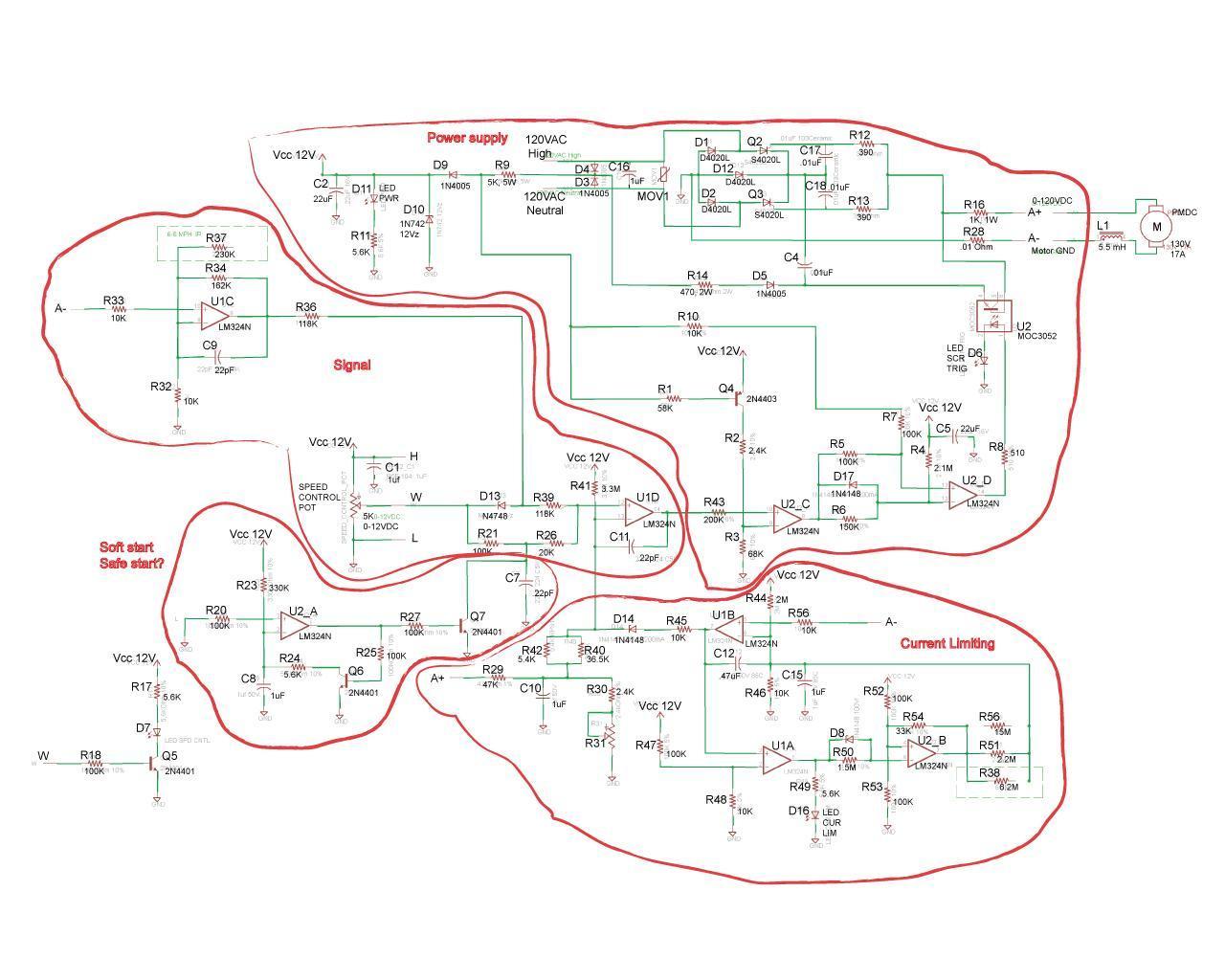
A search on line for treadmill speed control schematics and I find this: Notice 5K pot
5.7 is well within 20% of 5 so I'm with you on that one John.
Furthermore, this application is just like I described earlier - it's just being used as a voltage divider with one end at circuit voltage and the other at ground. If this circuit is anything like the subject circuit, 5K should work just fine.
from that schematic the 5k pot looks like its being used as a voltage divider to me, i would run what ever pot you have between 5k-100k
@Susquatch, i agree, i do have a hazy memory of 5.7k pots being a thing.....buts its been a solid 20 years since i took electronics, so maybe im just dreaming
@Susquatch, i agree, i do have a hazy memory of 5.7k pots being a thing.....buts its been a solid 20 years since i took electronics, so maybe im just dreaming
A search on line for treadmill speed control schematics and I find this: Notice 5K pot!
Btw, that's what I call a REALLY COOL block diagram you did! I love it!
DPittman
Ultra Member
So forgive my complete and utter ignorance about pretty much anything electrical but...
In my application of attempting to use a treadmill controller board and motor for the sewing machine I am trying to get a foot controlled apparatus made for the potentiometer....
The treadmill motor original circuitry does not start the motor until about 20-30% crank up of the potentiometer but then once it's rolling it can be cranked down some and continue to run. This is not ideal for my sewing machine application as I don’t want too big of a "dead" spot in the pedal travel to start.
So if I use a 5k pot instead of a 10k will that allow more voltage with less travel and there by result in less foot pedal travel to get the motor rolling?
testing would prove it, but i believe it would be the same the voltage divider (pot) its just a reference to the op amp circuitry, changing the value of the pot doesn't really do anything for what the op amp see's, its going to be a linear scale no matter what
my bet would be that the pulse width is not wide enough at the very low end to overcome what ever friction/inertia is required to start the motor rotating, but once the motor is rotating you dont need that initial "kick" to get it going any more and that is why you can slow it down below where you are able to get the motor started
im not to sure what the solution would be, maybe gear reduction to allow that higher initial rpm to be use full ? or possibly there may be a way to do it with discrete components that allows you to give the motor the initial pulse width to get it going and immediately drop back to where you're pot is.....however that's definitely beyond my skills.....with some playing around you might be able to code a microcontroller to give it that initial bump for the first few milliseconds
that circuit from what knowledge i have is just a simple pwm deal, nothing fancy....5% voltage divider in (pot) 5% pwm out kinda thing