• Scam Alert. Members are reminded to NOT send money to buy anything. Don't buy things remote and have it shipped - go get it yourself, pay in person, and take your equipment with you. Scammers have burned people on this forum. Urgency, secrecy, excuses, selling for friend, newish members, FUD, are RED FLAGS. A video conference call is not adequate assurance. Face to face interactions are required. Please report suspicions to the forum admins. Stay Safe - anyone can get scammed.

DMC2 Mini Mill - build and review

Mike R

Well-Known Member
Premium Member
So I decided to buy a new machine. Its going to arrive hopefully tomorrow and I'll pick it up from the UPS store.

Its a DMC2 Mini Mill from https://shariffdmc.com

A bit of background storytelling on why I want (need?) this machine.

I converted a ZAY 12Z mill (RF45 type) to CNC back in 2010.

What I didn't know about CNC vs what I thought I knew about CNC machines - well you can guess, but I sure did learn a lot over the years.

Long story short - it works, has had many updates, but still leaves me wanting a machine that won't eat 3mm endmills just by looking at them. i.e. it can't do small stuff due to backlash, yes even with backlash compensation. Its just too sloppy and variable depending on where in its travel it is. (single ball nuts), and the spindle speed is too low.
I don't have it in me to tear it all apart and replace the ballscrews and nuts (and probably mounts) with new double ball nuts. Maybe once I have a 2nd milling machine...

I want to machine small things - little IC engines, bits for steam locomotives, etc. A desktop CNC seems to fit the bill there. And I'd been looking at the various router options but didn't think a cnc router was what I really wanted.
I helped someone spec out and build a Taig CNC mill just 2 years ago, they bought the Taig 5019CR micro mill and I helped them through the stepper motor and control selection and setup. Its a nice little machine but still seemed to be missing something.

And then I saw it. Youtube knew what I needed in my life - a gapping hole in my wallet and another project I don't have enough time for.

Things that this machine ticked boxes for me, that seemed to be missing in other machines:
1. enclosure - keeps most chips in. I know it won't keep them all in, but reducing the area impacted is nice.
2. proper way covers on Y axis ways and ballscrew. X and Z are elevated so not as directly impacted.
3. ability to run coolant. (coolant pump included)
4. proper oiling system
5. proper high speed variable speed spindle (ER20)
6. Claimed ability to run very small cutters / small resolution (0.1mm end mill shown in youtube video )
7. Modest price* $3400 Cad plus shipping ($250) and taxes. Not thrilled with the shipping but I'd be out a full day from work and $100 in gas to go pick it up (5hr drive each way). And it still needs a controller* - more on that later, but for the price it seems like I'd be most of the way there in terms of dollars spent if I tried to build this myself from parts I order off of Amazon or AliExpress (that thought did cross my mind several times).

Additionally - this has a real human admitting their 1st design left some room for improvement and using the feedback to improve the offering and explaining why its a better design (not just stating "new and improved")

Regardless - I'm now on this path so we'll see how it goes. Hopefully I can provide a timely update on my progress as I build and then test this thing out and my ramblings will be of use to someone else.

Mike
 
That is an interesting machine, I'm looking forward to seeing how it works out.

Part of me wants to pull the trigger, the other part is doubtful about linear bearing quality, run out of collets, spindle quality etc. I also am curious how they create flatness (a linear bearing doesn't create flatness, it will bend to whatever its bolted do).

They are local for me, i wonder if they'd demo it? I found this overview of the machine, by I'm guessing the founder, which I found impressive. Impressive in the sense of he's well spoken and seems to have wrestled through all the challenges of design and bringing a complex product to market. No small feat.

I also start thinking what if you welded the frame, stress relieved it, scraped or ground the mounting points for flatness, filled it with epoxy granite for damping etc.... but maybe it makes more sense to use it as and just take light cuts and think of it like 3D printing ..... who cares how long it takes.
 
Last edited:
CanCam in TO also had a model like that at one time. Before I bought my laser I was looking at their version of this unit to do my deep engraving and so on. I was very disappointed with their samples. Perhaps I was expecting too much and the stuff I wanted it for was very small like logos and so on but it was very rough! Maybe they didn't know how to run it either!

I hope yours works out well for you, post some video of it running!
 
Well, 5 of 6 pieces showed up today, but the missing one is my fault for trying to redirect the shipment to a UPS store for pickup. Only 1 piece got redirected while the rest got dropped on my front step with just a doorbell ring according to my wife, no signature required these days I guess.
That's alright though, I need to make room for it in the shop - there are no free flat spaces at the moment (never are...)
IMG_1234.jpg
 
That is an interesting machine, I'm looking forward to seeing how it works out.

Part of me wants to pull the trigger, the other part is doubtful about linear bearing quality, run out of collets, spindle quality etc. I also am curious how they create flatness (a linear bearing doesn't create flatness, it will bend to whatever its bolted do).

They are local for me, i wonder if they'd demo it? I found this overview of the machine, by I'm guessing the founder, which I found impressive. Impressive in the sense of he's well spoken and seems to have wrestled through all the challenges of design and bringing a complex product to market. No small feat.

I also start thinking what if you welded the frame, stress relieved it, scraped or ground the mounting points for flatness, filled it with epoxy granite for damping etc.... but maybe it makes more sense to use it as and just take light cuts and think of it like 3D printing ..... who cares how long it takes.
I agree on the rails need a flat reference - to a degree. We'll see how it goes but in this case I think the rails are short enough and stout enough. Regardless I'll be tuning this up as I go and if I need to I can run the structure parts on my surface grinder to get a bit more flatness. Probably won't - I'd like to just build it as designed and see its performance for myself. If further improvements are needed I can go back later (yeah right...like that ever happens....)
 
Last box was picked up today. Got started on assembly. First issue was no instructions anywhere. Emailed the manufacturer at 4:00, got a response at 6:40 with a google drive link to the pdf instructions and other files.

First impressions:
Seems quite well thought out, and the assembly manual is quite detailed. I've got a fair bit of experience writing instructions, so I tend to nit pick, but so far up to step 10 (about 28 pages in) I've only noted 2 areas that could be improved (one is the text tells you that the render can be ignored and install the bolts from the other side foe ease of tightening later - should be fixed as reading is usually skipped...) , and another place where there should be a helpful note that the bolt doesn't pass through but rather goes to a threaded hole that is blocked (for pushing the plate into alignment). As I said, for me I find that a relatively good score.

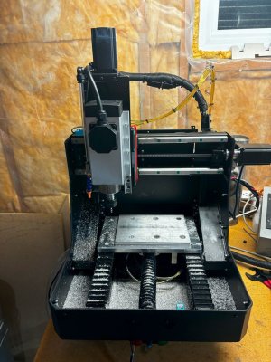
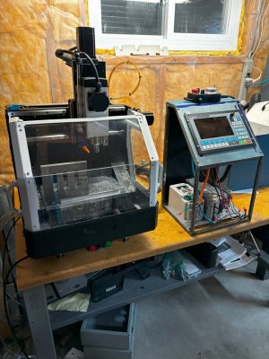
Here is where it stands as of now. Not aligned really at this point, its all loose and roughly aligned. There are a lot of fasteners in this thing but it does have a good mass to it.
Reading ahead the next steps are the linear rail installation, and then ballscrew assembly and mounting.

I've been taking video as I go, maybe I'll put together a Youtube video of it eventually (mostly time lapse video as the progress below was made over 2 hours....).
IMG_1263.jpg
IMG_1264.jpg
IMG_1266.jpg
 
Last box was picked up today. Got started on assembly. First issue was no instructions anywhere. Emailed the manufacturer at 4:00, got a response at 6:40 with a google drive link to the pdf instructions and other files.

First impressions:
Seems quite well thought out, and the assembly manual is quite detailed. I've got a fair bit of experience writing instructions, so I tend to nit pick, but so far up to step 10 (about 28 pages in) I've only noted 2 areas that could be improved (one is the text tells you that the render can be ignored and install the bolts from the other side foe ease of tightening later - should be fixed as reading is usually skipped...) , and another place where there should be a helpful note that the bolt doesn't pass through but rather goes to a threaded hole that is blocked (for pushing the plate into alignment). As I said, for me I find that a relatively good score.

Here is where it stands as of now. Not aligned really at this point, its all loose and roughly aligned. There are a lot of fasteners in this thing but it does have a good mass to it.
Reading ahead the next steps are the linear rail installation, and then ballscrew assembly and mounting.

I've been taking video as I go, maybe I'll put together a Youtube video of it eventually (mostly time lapse video as the progress below was made over 2 hours....).
View attachment 51926View attachment 51928View attachment 51929
Nice that it can be built quickly
 
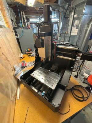
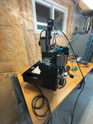
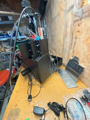
So the build continues. I'm about basically done the mechanical stuff (frame, enclosure), need to connect the oil lines and most of the electrical still.
I did have a snafu that was my fault.
I guess I lost focus at some point and missed a key instruction on tightening some fasteners that were instructed to be kept loose till later. I finally realized my error when I was installing the enclosure and nudged a loose bolt, and realized there was no way to tighten it. Went back and checked the manual before throwing blame anywhere and sure enough there was a whole page about tightening the screws.
Only lost about 2 hours or so there. I also corrected a mistake where I installed the side angled cover plates butted up to the triangular gusset plates faces as opposed to overhanging it, that is one that I put some blame on the manual - the image for the step is only a cad rendering and the way its shown the line used to create a curved surface can also look like the seam line between to pieces.

So far my critiques are as follows:
minor items:
The manual needs better diagrams for exploded views - would be a big benefit to the end assembler.
No packing list - so can't really know if you ever got the part (i.e. inventory when received)
- i.e. I think I'm missing a few little things that I was able to supply myself (piece of heat shrink, length of wire for power supply)
- also seem to be missing a small wire with special connector to the breakout board but not going to worry about it(see below)
-Superfluous break out board.
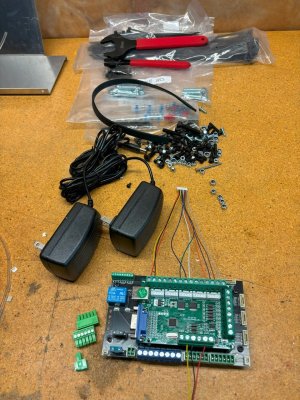
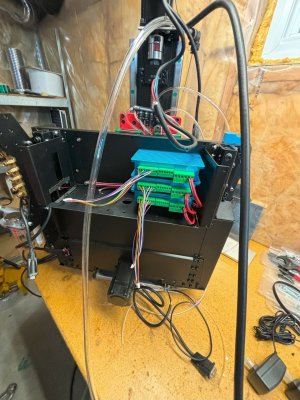
Ok I need to vent here. I knew from when I bought this machine that I had zero intent of using Mach3 to actually run it, even though it is supplied with a Mach3 specific break out board (USB connection that needs a Mach3 plugin to work). Thing is the machine has -2- break out boards. The Mach3 board sits on top of the proprietary DMC2 Mini break out board. As best as I can tell the DMC break out board serves as a fuse holder, barrel connector holder for the coolant pump power and stepper driver/board logic power (2 different identical wall warts), and a relay holder for the coolant pump, but adds a whole layer of complexity to the machine that is not needed. A quality break out board would serve the purpose and be 1 piece, with less connections (points of failure).
I started to wire it up just to prove it out with Mach3 until I bought a different controller but gave up quickly due to the very fine wire gauge used (28 AWG) which made connecting to the screw terminals just that little bit more difficult, and the fact that I am missing 1 of the required cables that connects to the DMC breakout board. I'm now expecting a new little stand alone controller in the mail tomorrow that I'll wire up in place of both boards.

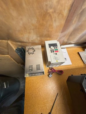
My last gripe about the machine is a design / creative marketing issue. The VFD for the spindle and the stepper motor power supply are not machine mounted, they are just loose items that you are to find mounting locations for (presumably a nearby wall).
So the small footprint described does not include these 2 items. I can deal with it but would have been better to be upfront about it. Its also possibly done (speculating here) so that the machine is not actually supplied as a device with electrical power - that is left to the buyer to figure out and therefore the product doesn't fall into regulatory hell of safety certifications.
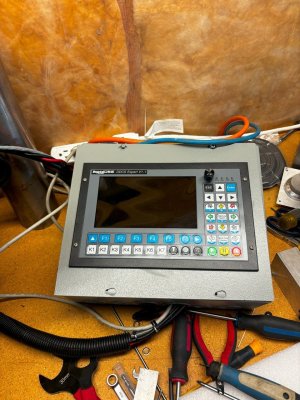
So along with the VFD and power supplies I'll need to figure out where to mount the controller with its display.

An top of this - an opportunity to pick up a Tormach 1100 with ATC and full enclosure for a very good price has presented itself - likely going to be replacing the machine that drove me to buy this... maybe both will stay with me, time will tell.
IMG_1319.jpgIMG_1325.jpgIMG_1326.jpgIMG_1328.jpgIMG_1327.jpgIMG_1329.jpg
 
I am getting there. I'm squaring the machine up, and its a bit tricky. It does have the ability to be done once assembled, but its still not easy.
The majority of the adjustment is done at the connection between the X-axis rails and the vertical posts. Effectively you are tweaking the entire plane that is the X -axis - both as X relative to Y travel but also Z relative to Y. Also the instructions did not go into detail on this, they seem to stop at the point of using a digital protractor to set the angle and assume that is sufficient. In my opinion its not for a machine advertised as a mill.

Anyways I got the thing adjusted in Z to be within 0.04mm over its ~175mm travel at both ends of the X-axis (i.e. no twist in X-axis) but then found out I was off a big amount in the squareness of X to Y, so all that goes out the window as I bring that back in line.
I've now aligned it in X and Y and did a test cut (just lightly glued a scrap plate down to the bed) and its as perfectly square as I can verify on the machine, so now I can make very small adjustments to Z perpendicularity if needed but I used a home made cylinder square to align the top and bottom x-axis rails so that should have got me very close. The head can also adjust twisting left to right when look at from the front so that will be the last adjustment.

I also checked the bed relative to the X and Y axis travel for flatness. Out of the box its also pretty good - max deviation was 0.05mm (~0.002"). By design this is to be flattened once the machine is working, the top bed plate is effectively an aluminum spoil board.

I did not use the Mach3 breakout board as as such I have some things I need to go back and revisit - I'm not happy with my control cabinets - i had to use 2 and they were just too small but it was stuff I had lying around. I really need to make a proper little cabinet. Also some of the wiring is pretty half assed. Definitely need to revisit that - again my choice of wiring driven by what was handy, not what would be best. The wires are too stiff and the cabinets too light so they get pushed around by the stiff wires...

I should also mention that it is stupid fast for such a small machine. I programmed the max velocity at 10000mm/min (393in/min) based on specs on the sellers website and I set acceleration to 1G and it just rocks. I'm probably going to set it to 50-60% of that for normal running just to keep the loads down and not abuse the machine.

Generally happy so far.
I have a few complaints, mostly related to the instructions and order of operations, but no deal breakers, no buyers remorse yet.
I do still need to actually use it to make something - we'll see if I can sneak in a few small parts that can run while I clean up the shop and get ready for the next big thing to show up...


IMG_1370.jpgIMG_1371.jpgIMG_1372.jpg
 
Hello Mike,

Thank you for the thread, it's very informative !
I wonder: Do you think that someone without prior experience would be able to build it ?
Thanks !
 
Hello Mike,

Thank you for the thread, it's very informative !
I wonder: Do you think that someone without prior experience would be able to build it ?
Thanks !
That's a tough one to answer.

By experience I am assuming that you are referring to machining experience?

Heres' my opinion.
A person without machining experience could build it following the provided instructions yes. The shortcomings I feel are mostly documentation related and could be resolved with a bit more guidance (even a you tube video link to show the processes for some of them)
In short the things will trip up an inexperienced person:
Squaring up the machine to a point where it will make good parts, and trying to use anything other than Mach3 to control it and troubleshooting if it doesn't work.

1. The instructions have the builder check the squareness of the build using a digital angle gauge. That might be fine for a router but for a mill I expect to check using a dial test indicator and a proper square. Having this step done as instructed could lead to some part issues later on that are not understood by the operator to be caused by the machines alignment.

2. IF you stick to using Mach3 (which a license and a PC for is not provided) then the configuration is all done for you as provided files. If you choose to use a different control method, then the parameters that you need to enter are not provided in a text / tabular form and you need to know what to look for to configure. Some of it is provide but its scattered throughout or you need to go back to the website to find the machine specs.
Things such as:
Steps per rev of motor, micro stepping of drive, lead screw pitch per rev, max acceleration, max velocity, max travels (for soft limits),
For example the stepper motor drives did not come with any documentation, and the builder is simply instructed to set the switches on it in accordance with the picture. Now the outside of the drive does list the switch functions so not a terrible inconvenience until you realize that you can't see the side with that info when the drive is mounted in the machine! Also, to setup another controller you need to know not only the drives setting (micro stepping setup - in this case 1600) - again there is more info that is assumed to be known. The drive says 1600 and that is assuming the motor is a 200 step per rev motor (it is the most common). These being closed loop motor and drive I assumed they are matched.
The VFD did come with a manual so that helped with configuring a different controller.

3. There is no troubleshooting guide. This would be handy for inexperienced and experienced assemblers alike, with common issues and solutions. i.e. spindle turns wrong way, steppers fault right away, motion is binding, etc. FYI - I had all these - all were simple fixes but knowing what to look for is key... that is where the guide or experience comes in.

Lastly, you need to assemble the machine with the instructions open on a PC as a lot of info is conveyed by photographs that rely on colour, where the addition of a simple table would allow the instructions to be printed in black and white (i.e pin 1 = orange = Pul+, pin 2 = blue = Pul-, etc), and / or a proper wiring diagram would be nice!

Hope that helps.
Mike
 
No encoder on the spindle, its a high speed spindle, 24000 rpm max and probably limited to ~8000 rpm on the low end (need to check that). But can quite likely do thread milling.
 
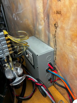
Well, I wasn't thrilled with my previous half assed attempt to enclose the controller, power supplies and VFD so I had another go at it.
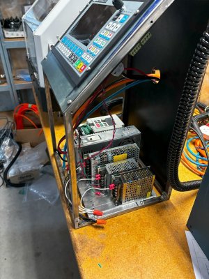
This one is much better. Not done yet - waiting on some connectors from Aliexpress as I want to be able to move this thing around and having the controller be able to be separate from the mill really helps with portability.
Here it is with its panels off and many wires disconnected for now. The 45º angle nicely matches the machine itself and helps with viewing. Its also heavy enough to not move when pushing buttons but not so heavy to be hard to carry. It made mostly from scrap, with the exception of the steel frame, had to buy the steel for that and the panel the controller is in was from a bought sheet that was just sitting around, its original use forgotten.
Its going to end up with a small opening at the top sides as those panels were about 1-1/2" short, but that can be for ventilation. I may need to put in a vent and or fan at the bottom but I want to use it first just to see how warm it does get. I could optimize things more but again was using whats on hand. The need for a variety of power supplies always catches me when looking at building a machine. In this case:
36V for the steppers (biggest one)
24VDC for the I/O on the controller (this one is way oversize at 6.5A but was on hand)
24VDC for the controller logic (was recommended to be separate from the I/O power)
and finally 12VDC for the coolant pump.

IMG_1598.jpgIMG_1599.jpg
 
Nicely done so far.

Having built the Gingery Lathe from castings and CRS, I believe the biggest undocumented feature of this mill will be vibration. The lack of mass was a common complaint for all the Gingery projects and certainly is for my lathe.

I'm not concerned about the linear bearings since even the HAAS use those. But what they mount to is likely going to be the biggest issue. Really looking forward to more reports on the operation.
 
So the build continues. I'm about basically done the mechanical stuff (frame, enclosure), need to connect the oil lines and most of the electrical still.
I did have a snafu that was my fault.
I guess I lost focus at some point and missed a key instruction on tightening some fasteners that were instructed to be kept loose till later. I finally realized my error when I was installing the enclosure and nudged a loose bolt, and realized there was no way to tighten it. Went back and checked the manual before throwing blame anywhere and sure enough there was a whole page about tightening the screws.
Only lost about 2 hours or so there. I also corrected a mistake where I installed the side angled cover plates butted up to the triangular gusset plates faces as opposed to overhanging it, that is one that I put some blame on the manual - the image for the step is only a cad rendering and the way its shown the line used to create a curved surface can also look like the seam line between to pieces.

So far my critiques are as follows:
minor items:
The manual needs better diagrams for exploded views - would be a big benefit to the end assembler.
No packing list - so can't really know if you ever got the part (i.e. inventory when received)
- i.e. I think I'm missing a few little things that I was able to supply myself (piece of heat shrink, length of wire for power supply)
- also seem to be missing a small wire with special connector to the breakout board but not going to worry about it(see below)
-Superfluous break out board.
Ok I need to vent here. I knew from when I bought this machine that I had zero intent of using Mach3 to actually run it, even though it is supplied with a Mach3 specific break out board (USB connection that needs a Mach3 plugin to work). Thing is the machine has -2- break out boards. The Mach3 board sits on top of the proprietary DMC2 Mini break out board. As best as I can tell the DMC break out board serves as a fuse holder, barrel connector holder for the coolant pump power and stepper driver/board logic power (2 different identical wall warts), and a relay holder for the coolant pump, but adds a whole layer of complexity to the machine that is not needed. A quality break out board would serve the purpose and be 1 piece, with less connections (points of failure).
I started to wire it up just to prove it out with Mach3 until I bought a different controller but gave up quickly due to the very fine wire gauge used (28 AWG) which made connecting to the screw terminals just that little bit more difficult, and the fact that I am missing 1 of the required cables that connects to the DMC breakout board. I'm now expecting a new little stand alone controller in the mail tomorrow that I'll wire up in place of both boards.

My last gripe about the machine is a design / creative marketing issue. The VFD for the spindle and the stepper motor power supply are not machine mounted, they are just loose items that you are to find mounting locations for (presumably a nearby wall).
So the small footprint described does not include these 2 items. I can deal with it but would have been better to be upfront about it. Its also possibly done (speculating here) so that the machine is not actually supplied as a device with electrical power - that is left to the buyer to figure out and therefore the product doesn't fall into regulatory hell of safety certifications.
So along with the VFD and power supplies I'll need to figure out where to mount the controller with its display.

An top of this - an opportunity to pick up a Tormach 1100 with ATC and full enclosure for a very good price has presented itself - likely going to be replacing the machine that drove me to buy this... maybe both will stay with me, time will tell.
View attachment 52182View attachment 52183View attachment 52184View attachment 52185View attachment 52186View attachment 52188
New follower: Have purchased same DMC2mini - got it all together but issues with no movement at all.
Using the mach3 board and software... Not sure if your familiar with long mill - but have put 2 of them together with
no issues - work beautiful... Any ideas what might be the issue? Seeing a lot of issues with mach3 -- Any improvements would be great!
Thank you
 
Back
Top