TorontoBuilder
Sapientia et Doctrina Stabilitas
Really!! That SUCKS! All our tablets are Samsung!
are all your tablets brand new?
I have two samsung tablets from 2015 tablet... and wife's brand new one.
Really!! That SUCKS! All our tablets are Samsung!
Really!! That SUCKS! All our tablets are Samsung!

BTW, I assembled my PC boards and bought Hammond boxes which I promptly tried the DRO out on to mill the D9 connector holes. Never again will I spin & count to place dozens of datum locations using the dials and backlash!Adapter circuit card it will be!
Thanks for the heads up on Samsung, I'll have to check and see what I have. The other half is the Android literate person in our house so I will have knowledge handy.
Your wife lucks in!are all your tablets brand new?
I have two samsung tablets from 2015 tablet... and wife's brand new one.

are all your tablets brand new?
I have two samsung tablets from 2015 tablet... and wife's brand new one.

Never again will I spin & count to place dozens of datum locations using the dials and backlash!
This is something one cannot appreciate till you have one. The capability blew me away the very first time I used it. In fact, I used my X scale right after I installed it to help me make my Y sensor bracket. I had intended to use my crank dials for that purpose because I didn't trust the DRO yet. But the repeatabity and ease of use were compelling, so I plowed ahead and ONLY used the DRO. I even flipped the part so I could use X instead of Y. I've NEVER looked back going so far as to add a quill scale to my Z. The unit combines the quill and knee to read total Z.
I know my one is so old they no longer offer updates for it.No, actually nothing is new, not even the wife's. However, I diligently update them.
I know my one is so old they no longer offer updates for it.
FWIW if it runs min OS 5.0 it can still run TDRO although OS 8 is recommended if you were considering it.I have one like that too. I think it's time to let it die. Maybe let the grandkids destroy it.
I have no kids let alone grand kids.I have one like that too. I think it's time to let it die. Maybe let the grandkids destroy it.
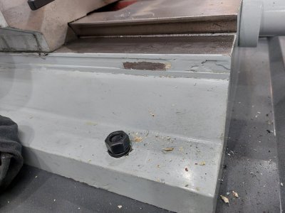
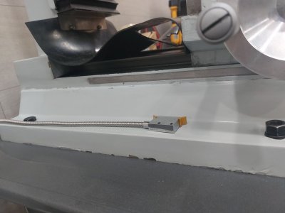
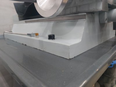
Joe, Would be willing to share your stl files?Just completed adding X,Y and Z axis DRO's to a CX601 mill. Tried to keep things very simple but still needed to maintain accuracy. Used self adhesive 10mm wide magnetic tape (1 micron) in a stainless/mag tape/stainless sandwich. Brackets are 3D printed and I may make from aluminum at a later date if needed. Adhesive is 3M VHB tape which is very strong and oil resistant. Removed the X and Z axis measuring tapes and reused the machined grooves for the magnetic tape.
Hopefully the following photos will be self explanatory.
Also just completed simple design for adding quill DRO and summing to Z axis. Will add photos later.
View attachment 31983View attachment 31982View attachment 31986
Joe,Just completed adding X,Y and Z axis DRO's to a CX601 mill. Tried to keep things very simple but still needed to maintain accuracy. Used self adhesive 10mm wide magnetic tape (1 micron) in a stainless/mag tape/stainless sandwich. Brackets are 3D printed and I may make from aluminum at a later date if needed. Adhesive is 3M VHB tape which is very strong and oil resistant. Removed the X and Z axis measuring tapes and reused the machined grooves for the magnetic tape.
Hopefully the following photos will be self explanatory.
Also just completed simple design for adding quill DRO and summing to Z axis. Will add photos later.
View attachment 31983View attachment 31982View attachment 31986
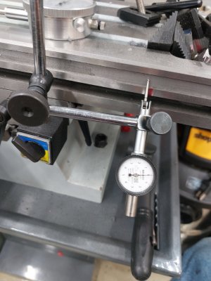
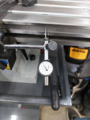
I'm about to install the 1um tape to the cx601 and was checking the "trueness" of the groove cut for the measuring tape. The magnetic tape will fit very well as previously said in this thread. My question is will the 0.003"-0.004" variation in x travel going to put an error in the touch dro positioning of any significance ( It will result in a change in the gap between the read head and the tape)?