• Spring 2024 meetup in Calgary - date Saturday, April 20/2024. discussion Please RSVP Here to confirm and get your invitation and the location details. RSVP NOW so organizers can plan to get sufficient food etc. It's Tomorrow Saturday! you can still RSVP until I stop checking my phone tomorrow More info and agenda
  • We are having email/registration problems again. Diagnosis is underway. New users sorry if you are having trouble getting registered. We are exploring different options to get registered. Contact the forum via another member or on facebook if you're stuck. Update -> we think it is fixed. Let us know if not.
  • Spring meet up in Ontario, April 6/2024. NEW LOCATION See Post #31 Discussion AND THE NEW LOCATION

Colchester Student, Kingston $200

B Vader

Active Member
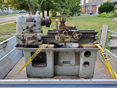
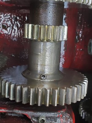
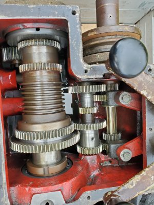
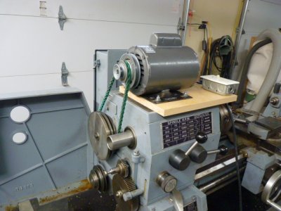
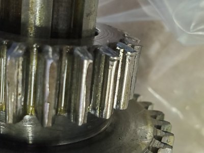
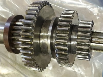
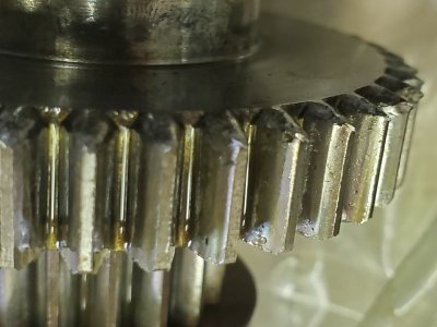
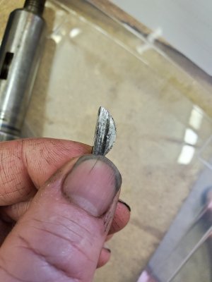
I got the lathe home yesterday. After checking it over more noticed when rolling the drive pulley over back and forth, there was quite a bit of backlash. Pulled the top cover off the headstock to inspect. The backlash appears to be in the gears on the 1st and 2nd shaft inside. I believe the manual described this as shaft A and B. Also noticed on the B shaft the Set screw in the gear was tight to shaft but looked like thread in gear was worn(was moving). There was lots of burrs on the gear teeth probably from engaging the speed selector while still in motion. Oil was low in the gearhead, oil laying in the chip try so seals must be leaking from the headstock, gearbox and apron.
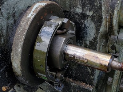
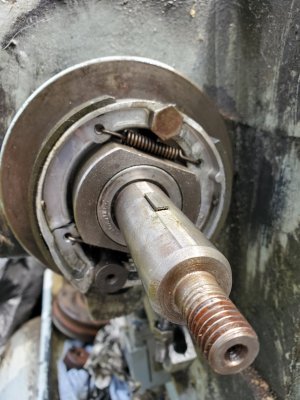
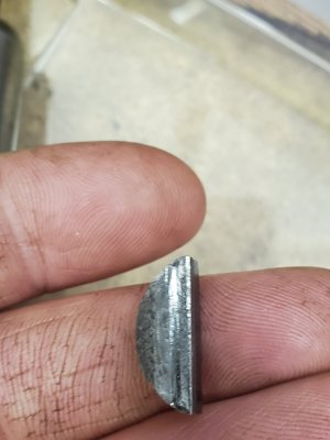
Other issues so far are: 1. cracked brake shoe, 2. no drive motor 3. possible the incorrect pulley for drive motor 4. wiring disconnected and possible some missing electrical components. 5. Missing spanner for chuck and missing motor compartment cover.
My plan next is to flush out the gearhead, get a motor and pulley to run it and see if there are any other issues before going further.
Would anyone have the specs of the pulley diameter of the motor pulley for this machine?
 

Attachments

  • 20210809_193229.jpg
    20210809_193229.jpg
    735.1 KB · Views: 22
  • 20210810_194708.jpg
    20210810_194708.jpg
    523.5 KB · Views: 21
  • 20210810_122028.jpg
    20210810_122028.jpg
    595.7 KB · Views: 22
  • 20210810_123640.jpg
    20210810_123640.jpg
    580.5 KB · Views: 20
  • 20210810_130034.jpg
    20210810_130034.jpg
    370.9 KB · Views: 20

RobinHood

Ultra Member
Premium Member
On page 19 of the parts section in this manual

http://manuals.chudov.com/Clausing/Colchester-Student-Lathe-Manual.pdf

there is a picture of the motor pulley. The drawings are to scale. It would give you a rough idea of the size if you measure the motor mount platform and compare the size of the pulley to it.

They used different size pulleys for 50 vs 60 Hz motors.

Next step would be to calculate the size based on motor rpm and gear ratios to achieve the posted speeds.

If you plan on using a 3 phase motor with a VFD, you don’t have to be too concerned with the actual pulley size. As long as you are ballpark, you can do the rest with the VFD.
 

B Vader

Active Member
Thanks for the pulley info.
This lathe has a control board with just the ON/OFF selector switch and no forward /reverse. Does the VFD give Forward/Reverse operation as well?
I am currently putting together a 7.5 HP rotary phase converter for a milling machine I have bought and was planning on using it for the lathe as well. Perhaps using the VFD is the preferred option.
 

RobinHood

Ultra Member
Premium Member
If you are going the RPC route, then you will need a FWD / REV switch in addition to the ON/OFF presently on the lathe.

The RPC option requires the motor pulley to be accurately dimensioned if you are aiming for the speeds as posted. You could work backwards from the desired spindle speed (as posted), see which gears are in mesh, count the teeth and determine the input shaft RPM required to give that posted spindle speed. Do that for a few spindle speeds. Average the input shaft RPM (they will be very close for all the selected speeds). Now measure the input shaft pulley and determine the motor pulley size based on input shaft rpm, motor rpm and input shaft pulley size.

A VFD has the FWD/REV function built in. For convenience, if you want to have the FWD/REV switch close to the operator’s position, you’ll end up with a remote switch for the VFD anyway.

So either way, you will probably require a FWD/REV switch.
 

YotaBota

Mike
Premium Member
Can you do something like this just to do some test runs? For $200 I don't think you went wrong, ya it will take some work but the end result will be worth it.
 

Attachments

  • P1010740.JPG
    P1010740.JPG
    164.9 KB · Views: 8

B Vader

Active Member
Can you do something like this just to do some test runs? For $200 I don't think you went wrong, ya it will take some work but the end result will be worth it.
Yes that sounds like a great idea. I know someone that has a single phase motor, just will need a pulley to correct the speeds a little closer to specs.

I did remove the input pulley and shaft A to check closer on the spur gear teeth. They do have a lot of sharp burrs. Is this something that will cause problems down the road and should be addressed? Thinking the burrs could be filed off.
Also found the drive pulley woodruff key was quite worn so that accounts for some of that backlash I was feeling in the drive.
 

Attachments

  • 20210811_111202.jpg
    20210811_111202.jpg
    336.9 KB · Views: 15
  • 20210811_111216.jpg
    20210811_111216.jpg
    496.2 KB · Views: 15
  • 20210811_111222.jpg
    20210811_111222.jpg
    329 KB · Views: 15
  • 20210811_123452.jpg
    20210811_123452.jpg
    318.5 KB · Views: 15
  • 20210811_123523.jpg
    20210811_123523.jpg
    263.9 KB · Views: 14

B Vader

Active Member
If you are going the RPC route, then you will need a FWD / REV switch in addition to the ON/OFF presently on the lathe.

The RPC option requires the motor pulley to be accurately dimensioned if you are aiming for the speeds as posted. You could work backwards from the desired spindle speed (as posted), see which gears are in mesh, count the teeth and determine the input shaft RPM required to give that posted spindle speed. Do that for a few spindle speeds. Average the input shaft RPM (they will be very close for all the selected speeds). Now measure the input shaft pulley and determine the motor pulley size based on input shaft rpm, motor rpm and input shaft pulley size.

A VFD has the FWD/REV function built in. For convenience, if you want to have the FWD/REV switch close to the operator’s position, you’ll end up with a remote switch for the VFD anyway.

So either way, you will probably require a FWD/REV switch.

I will keep my eyes open for one. Thanks for the help with the controls and pulley dimensions/speed.:)
 

YotaBota

Mike
Premium Member
As long as your motor rpm (1750ish) and the pulley is close you'll be okay. I used this setup because there was no 3phase available I just wanted to here the sound of the headstock. My motor is a .5hp and it spun the SM easily even at the higher rpms.
Edit - I just looked closer at the pictures of the gears, someone has not been kind to the machine. Since you have it torn apart, now is the time to clean up the teeth and reshape if needed. I would imagine it's fairly noisy with the teeth looking the way the are.
 
Last edited:

RobinHood

Ultra Member
Premium Member
I agree on deburring the gears while they are out. The flanks look in good shape, so once the “uglies” are off the teeth, your machine should have many more years of service life left.
 

B Vader

Active Member
As long as your motor rpm (1750ish) and the pulley is close you'll be okay. I used this setup because there was no 3phase available I just wanted to here the sound of the headstock. My motor is a .5hp and it spun the SM easily even at the higher rpms.
Edit - I just looked closer at the pictures of the gears, someone has not been kind to the machine. Since you have it torn apart, now is the time to clean up the teeth and reshape if needed. I would imagine it's fairly noisy with the teeth looking the way the are.
Prior to flushing out the gearbox I ran a magnet around the bottom of the gearbox and pulled out a lot of metal filings. Flushed out with varsol, installed input drive shaft assembly and filled with oil. Decided to run the lathe as was suggested to see how the headstock sounded. A lot of vibration at the top speed and declining in volume as speeds are reduced. Vibration increased while applying resistance to the feed lever when running the feed shaft to the saddle. I initial inspection of the 2nd (B) shaft showed the most wear of the spur gear teeth and one gear particularly loose on shaft. Thinking that might be the source of most of the noise.
I even was able to stall/stop the feed shaft out of the feed box when applying resistance against the feed lever and the end gears were still turning. Don't think this is normal but I am not experienced with these machines. Will test run some more tomorrow.
Also noticed a lot of oil slinging off the drive pulley. Oil getting by the seal, shaft was worn by .008" from the seal contact.
 

RobinHood

Ultra Member
Premium Member
There is a shear pin in the gear drive train - check your manual.

There is also a slip clutch in the apron - factory preset to 350lbs. It is adjustable - see excerpt from the manual below.
8D981CE1-E780-4526-934C-2566723038C9.jpeg

If the drive train was overloaded enough with an incorrect grade shear pin in place, there could be another pin/key sheared in the QCGB. Check everything, assume nothing. It is the only way you will know for sure what is going on.
 

B Vader

Active Member
I will check that out. Don't see that adjustment on my lathe. Contacted Colchester they sent me a manual for my 1955 lathe based on serial number but looks like different than the one you have shown in that manual. Will investigate further into the drive system to figure this out.
 

RobinHood

Ultra Member
Premium Member
That is very nice of Colchester.

If they sent you a manual based on the serial number - disregard my info, it was just a generic search for a Roundhead. Go with what your manual says.

Keep us posted how you make out.
 

B Vader

Active Member
Here is a copy of this manual if anyone has a similar age machine. Serial # 25806. 1000 rpm top speed on headstock.
 

Attachments

  • Student (old) Serial No F2 20551-32174.pdf
    3.2 MB · Views: 8

RobinHood

Ultra Member
Premium Member
You do have a clutch at the feed box and a shear pin in the gear train. I have not yet figured out how it works. Could explain why even though gear train is turning, the feed is not working if the clutch is slipping.

The boxed paragraphs are from your manual.
1EF97120-70BF-4491-B179-01D21E378773.jpeg
 

B Vader

Active Member
I just read this section after getting home from work. Will check it out tomorrow morning. Maybe just that simple.
 

Dabbler

ersatz engineer
@B Vader I missed this thread last summer - fantastic find! (and a nice project, too).

You will be very happy with it when it all comes together...
 
Top