• Spring 2024 meetup in Calgary - date Saturday, April 20/2024. discussion Please RSVP Here to confirm and get your invitation and the location details. RSVP NOW so organizers can plan to get sufficient food etc. One week to go! More info and agenda
  • We are having email/registration problems again. Diagnosis is underway. New users sorry if you are having trouble getting registered. We are exploring different options to get registered. Contact the forum via another member or on facebook if you're stuck. Update -> we think it is fixed. Let us know if not.
  • Spring meet up in Ontario, April 6/2024. NEW LOCATION See Post #31 Discussion AND THE NEW LOCATION

Co-located Hall Effect Sensor minimum separation distance

TorontoBuilder

Ultra Member
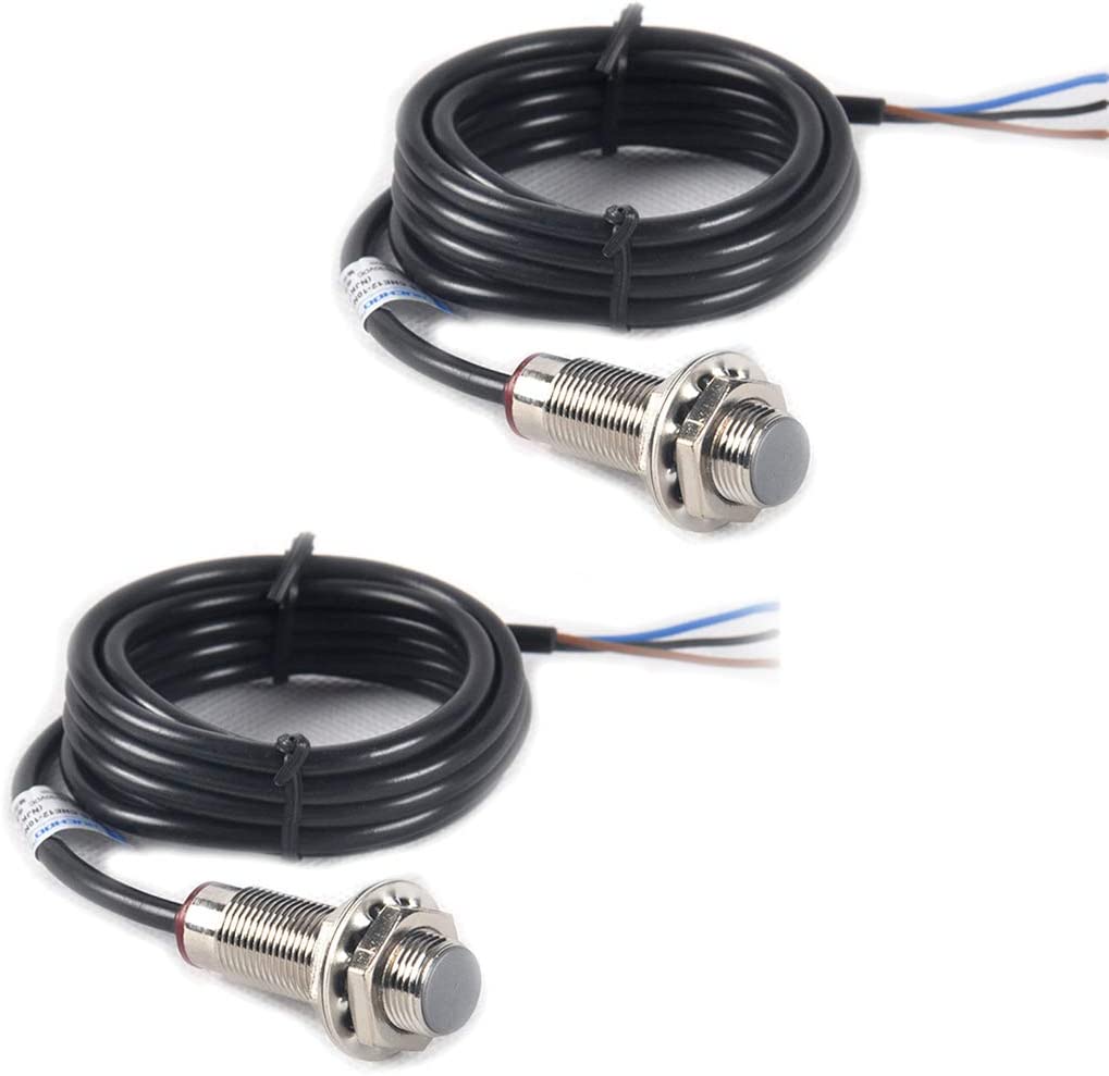
Has anyone used multiples of the typical hall effect sensor on the same spindle? Those typical cheap sensors with a detection distance of 10mm.

If so, how far apart did you place the read heads so they did not interfere with each other? I'm hoping 25 mm will suffice.


61-i7mc1CbL._AC_SL1100_.jpg
 

PaulL

Technologist at Large
Premium Member
I've never had to separate Hall effect sensors due to interference. They might detect the same magnetic field, but that should be all.
Are you seeing an actual problem?
 

TorontoBuilder

Ultra Member
I've never had to separate Hall effect sensors due to interference. They might detect the same magnetic field, but that should be all.
Are you seeing an actual problem?

Thanks for the feedback Paul.

I haven't installed them yet, I wanted to preemptively avoid any possible issues in the design stage. I'll be making the mount and installing them on the lathe spindle today.
 

phaxtris

(Ryan)
Premium Member
Premium Member
Why 2? Is it for resolution ?

may be better off with an encoder ring, if that's the case. like the abs ring on an axle
 

TorontoBuilder

Ultra Member
Why 2? Is it for resolution ?

may be better off with an encoder ring, if that's the case. like the abs ring on an axle

As Paul said below, two sensors can be used to determine spindle rotation direction and that is a long term goal...

But currently a friend and I have developed a machining calculator that will be mounted on the lathe to which we just added a DRO. The DRO was ordered with a tachometer option as well. In operation we will use the DRO to display the RPM and the machining calculator to display surface feet per minute and feed rates.

by mounting two read heads going to two separate devices I can also compare the results, and tune and validate the programming of the machining calculator. Specifically to allow us to fine tune the buffering so as to display a stable and accurate reading.

For improved resolution we will be using an array with 5 magnets mounted on the spindle.
 

Susquatch

Ultra Member
Administrator
Moderator
Premium Member
For improved resolution we will be using an array with 5 magnets mounted on the spindle.

My preminary design has either 5, or 3 magnets. I wanted that so I could drill through to mount the magnets on the opposite inside of a piece of abs pipe bored to precisely fit the OD of the rear of my spindle at 5 or 3 more opposite points and never worry about glue coming loose and flinging a magnet to Australia.

I am not concerned about knowing direction.
 

TorontoBuilder

Ultra Member
My preminary design has either 5, or 3 magnets. I wanted that so I could drill through to mount the magnets on the opposite inside of a piece of abs pipe bored to precisely fit the OD of the rear of my spindle at 5 or 3 more opposite points and never worry about glue coming loose and flinging a magnet to Australia.

I am not concerned about knowing direction.

I'm making an inner ring like the race on ball bearings bored to spindle OD, and an outer ring bored to the OD of the inner ring, that slips over the inner ring to retain the magnets in the event of failed epoxy.

I will drill space for magnets in the inner ring, stick them in place with tiny bit of epoxy, and then slide outer ring over that and then grub screws retain this assembly on the spindle. I copied what you have mentioned previously. I hope I understood your design intent.
 

Susquatch

Ultra Member
Administrator
Moderator
Premium Member
I'm making an inner ring like the race on ball bearings bored to spindle OD, and an outer ring bored to the OD of the inner ring, that slips over the inner ring to retain the magnets in the event of failed epoxy.

I will drill space for magnets in the inner ring, stick them in place with tiny bit of epoxy, and then slide outer ring over that and then grub screws retain this assembly on the spindle. I copied what you have mentioned previously. I hope I understood your design intent.

Yup, you understood perfectly. I originally wanted the double ring too. I've mostly decided to just do one ring with the magnets inside it because I'm a bit worried about the gap to the read head and the fragility of a thin ring. Drilled from the inside, I can make the gap as small as I want without introducing fragility. That gets traded off against the need for a long flat ended drill (or end mill).

I'm not decided yet. I'll be watching how you make out. I prefer the double ring if it can be made robust enough.

Right now I'm also thinking I'll pass on the grub screws too. I think a few dabs of gap style thread lock will be sufficient.
 

phaxtris

(Ryan)
Premium Member
Premium Member
Here's my thought, you could use an abs ring and two of those style sensors, resolution, direction sensing, and no concern for magnetic interference from the multiple magnets

Abs tone rings and sensors are easy to get, then a guy would just need to turn an adapter for your spindle and press or weld the ring to the adapter, and maybe a grub screw to hold on to your spindle outfeet?
 

TorontoBuilder

Ultra Member
Okay, I've designed a mount that will place the heads of the hall sensors ~1.125 inches apart and the bodies at 60 degrees to each other... I know terrible sketch but I was in a hurry hurry


1681175746076.png
 

TorontoBuilder

Ultra Member
Yup, you understood perfectly. I originally wanted the double ring too. I've mostly decided to just do one ring with the magnets inside it because I'm a bit worried about the gap to the read head and the fragility of a thin ring. Drilled from the inside, I can make the gap as small as I want without introducing fragility. That gets traded off against the need for a long flat ended drill (or end mill).

I'm not decided yet. I'll be watching how you make out. I prefer the double ring if it can be made robust enough.

Right now I'm also thinking I'll pass on the grub screws too. I think a few dabs of gap style thread lock will be sufficient.

I got one ring turned out of an old phenolic 24 tooth gear. With the DRO I was able to nail the diameter and get a nice snug fit on the spindle so I don't need a grub screw but I'll use one anyway since Tom may use the gear teeth for simple indexing as well. I could not see how to mill holes from the inside of the ring which is why I settled on the two ring arrangement.

Tomorrow I'll mill the pockets for the magnets 1.5 mm deep, 60 degrees apart, and glue the magnets in. Then make the outer ring. I'll epoxy the outer ring over the inner ring, then turn the outer diameter down further when the array is a single unit.

Sorry I was too busy to take pics... or rather too dirty to pull out my phone. I'll get some tomorrow
 

Susquatch

Ultra Member
Administrator
Moderator
Premium Member
I could not see how to mill holes from the inside of the ring which is why I settled on the two ring arrangement.

Not trying to change your mind here. Just telling you how I will do it IF I DO.

I had come up with the two ring design for exactly the same reason. A little while later I realized that by using an odd number of sensors you can drill or mill through from the opposite side of the ring. It leaves behind some empty holes, but so what. At a minimum, the empty holes tell you where the magnets are as they are half way between holes. But who knows, some stroke of innovation might find a use for them too.

I have not decided which approach to use yet. It's so nice to have you as my Guinea Pig...... ;). The pros and cons of your results and challenges will prolly dictate my final chosen direction.

It's also nice to be blessed with such a long rear spindle.
 

TorontoBuilder

Ultra Member
Not trying to change your mind here. Just telling you how I will do it IF I DO.

I had come up with the two ring design for exactly the same reason. A little while later I realized that by using an odd number of sensors you can drill or mill through from the opposite side of the ring. It leaves behind some empty holes, but so what. At a minimum, the empty holes tell you where the magnets are as they are half way between holes. But who knows, some stroke of innovation might find a use for them too.

I have not decided which approach to use yet. It's so nice to have you as my Guinea Pig...... ;). The pros and cons of your results and challenges will prolly dictate my final chosen direction.

It's also nice to be blessed with such a long rear spindle.

I'm not saying there is anything wrong with the drill thru method.

IF I had more material options I'd have gone that way and used narrower and thicker magnets. But I only had a limited supply of phenolic and two different types of magnets plus two tiny magnets I'd have liked to have tried if I'd had 9 of them.

Fewer magnets less resolution. I still plan to stick a big motor and high end VFD with an external braking resister on this lathe when Tom is not looking. This will be a forever lathe.
 

Susquatch

Ultra Member
Administrator
Moderator
Premium Member
I'm not saying there is anything wrong with the drill thru method.

IF I had more material options I'd have gone that way and used narrower and thicker magnets. But I only had a limited supply of phenolic and two different types of magnets plus two tiny magnets I'd have liked to have tried if I'd had 9 of them.

Fewer magnets less resolution. I still plan to stick a big motor and high end VFD with an external braking resister on this lathe when Tom is not looking. This will be a forever lathe.

You are having wwaaaaay too much fun!
 

TorontoBuilder

Ultra Member
You are having wwaaaaay too much fun!
no. in fact I hate large machines, I hate moving them around, hoisting them in the air, and trying not to trip over stuff as it has to be moved all around to provide the space to move big stuff. If someone were to say "here is a free Parker Majestic surface grinder for you to convert to cnc" I'd probably say no thanks right now.

I am just barely tolerating doing those things that must be done so I can get to the point I can do what is actually fun.
 

phaxtris

(Ryan)
Premium Member
Premium Member
What size magnets are you using? I have like 100 or so 8mmx3mm neodymium magnets, if that size would work I can toss the 9 you need in the post
 
Top