-
Scam Alert. Members are reminded to NOT send money to buy anything. Don't buy things remote and have it shipped - go get it yourself, pay in person, and take your equipment with you. Scammers have burned people on this forum. Urgency, secrecy, excuses, selling for friend, newish members, FUD, are RED FLAGS. A video conference call is not adequate assurance. Face to face interactions are required. Please report suspicions to the forum admins. Stay Safe - anyone can get scammed.
-
Several Regions have held meetups already, but others are being planned or are evaluating the interest. The Calgary Area Meetup is set for Saturday July 12th at 10am. The signup thread is here! Arbutus has also explored interest in a Fraser Valley meetup but it seems members either missed his thread or had other plans. Let him know if you are interested in a meetup later in the year by posting here! Slowpoke is trying to pull together an Ottawa area meetup later this summer. No date has been selected yet, so let him know if you are interested here! We are not aware of any other meetups being planned this year. If you are interested in doing something in your area, let everyone know and make it happen! Meetups are a great way to make new machining friends and get hands on help in your area. Don’t be shy, sign up and come, or plan your own meetup!
You are using an out of date browser. It may not display this or other websites correctly.
You should upgrade or use an alternative browser.
You should upgrade or use an alternative browser.
cnc, pattern, mold & aluminum casting
- Thread starter PeterT
- Start date
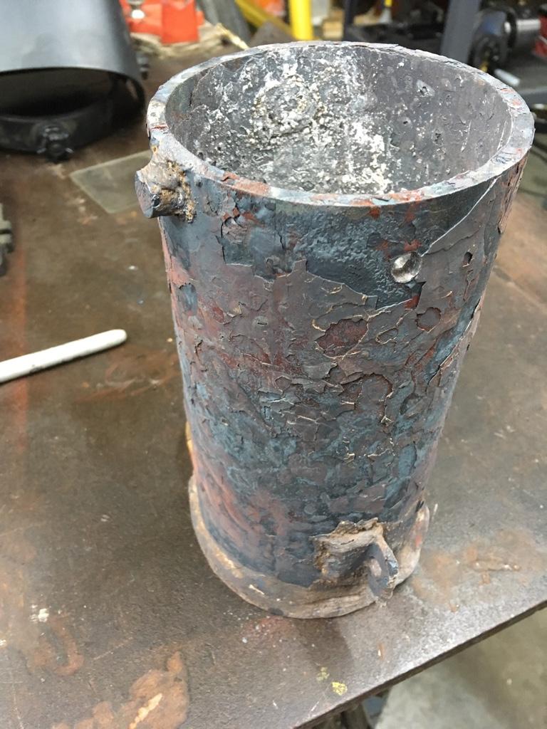
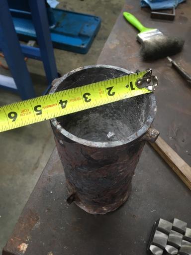
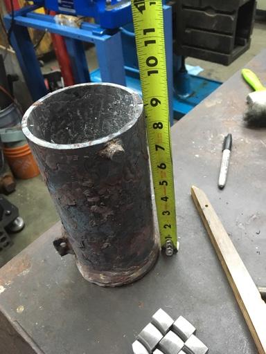
I've been asked to post my foundry adventures here rather than in my G3616 milling machine thread so here goes. I need to make a holder for my 4th axis Harmonic Drive AC Servo motor. However the #6 silicon carbide crucible is too small as is the #8. I really need at least 12 pounds based on what the CAD software tells me for total volume. So I'm making my first pipe crucible. The bottom plate was tig welded on by a friend who then also mounted it on his lathe and using MACH3 made the outside pretty.
Anyway the two studs will go on the sides and I'm going to use CNC to make the two lifting arms that fit onto the studs to be able to lift it out of the furnace and also serve as the pouring handle.
I first 3D printed one quarter of what it was I wanted and verified the harmonic drive would be properly held on the mill.

Next I 3D printed all four pieces to make sure it worked and to hold it so it wouldn't fall over while I tested the STMBL AC Sevo drive.

I still need to make a face plate for this to hold chucks etc. It will hold the faceplate from my Southbend Heavy 10L
Then re-drew the part with draft and shrinkage and 3D printed the 4 parts, glued them together and with body filler and primer and paint ended up with this.

And it does pull nicely from the green sand so all I need is the crucible and handle.

I'll post again when I pour it. I also have a couple of motor mount plates to pour that require the big crucible.
Anyway the two studs will go on the sides and I'm going to use CNC to make the two lifting arms that fit onto the studs to be able to lift it out of the furnace and also serve as the pouring handle.
I first 3D printed one quarter of what it was I wanted and verified the harmonic drive would be properly held on the mill.
Next I 3D printed all four pieces to make sure it worked and to hold it so it wouldn't fall over while I tested the STMBL AC Sevo drive.
I still need to make a face plate for this to hold chucks etc. It will hold the faceplate from my Southbend Heavy 10L
Then re-drew the part with draft and shrinkage and 3D printed the 4 parts, glued them together and with body filler and primer and paint ended up with this.
And it does pull nicely from the green sand so all I need is the crucible and handle.
I'll post again when I pour it. I also have a couple of motor mount plates to pour that require the big crucible.
Attachments

I went down a similar path , wanted a Frankenstein lug on either side, figured I would make a holder.......
But then I had a bad experience with my holder dropping 8lbs to the floor......... long story
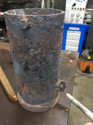
Here is a picture of my steel crucible that I’ve been using since 2001
U can see the lugs, never been used since. Instead I drilled a hole about 3/4 inch down and center ( see end of sharpie marker below)
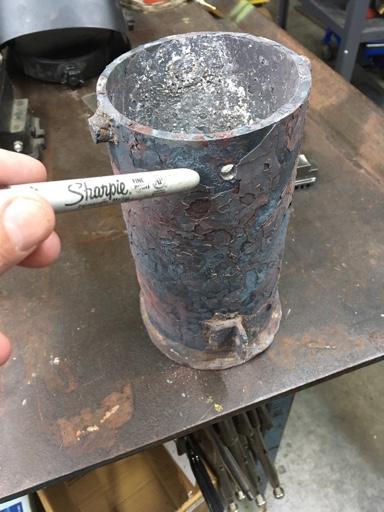
And I welded a tang at the bottom with a hole. (See image below)
Using some simple hooks I can lift and pour by hooking both holes and articulating the pot
It’s primitive but bullet proof
It is time for a new pot though...... looking forward to your experience
Sent from my iPhone using Tapatalk
But then I had a bad experience with my holder dropping 8lbs to the floor......... long story
Here is a picture of my steel crucible that I’ve been using since 2001
U can see the lugs, never been used since. Instead I drilled a hole about 3/4 inch down and center ( see end of sharpie marker below)
And I welded a tang at the bottom with a hole. (See image below)
Using some simple hooks I can lift and pour by hooking both holes and articulating the pot
It’s primitive but bullet proof
It is time for a new pot though...... looking forward to your experience
Sent from my iPhone using Tapatalk
Interesting approach using just the single hole at the top. My tangs have shoulders and theoretically the lift part will hook on and then mine will pivot down and hook at the bottom to a loop (Chain link) at the bottom.

This is just a trial on a piece of scrap milled with LinuxCNC. The first few inches of the angle would be cut away so that it can clear the sides of the furnace. The one on the right will be the mirror image.
My 6# is lifted with a different type of holder since the furnace body lifts up. I can pick it up and pour from the side. I will make the part that goes around the crucible removable and create a larger one for the #8.
Can you post some pics of your #6 holder?
Sent from my iPad using Tapatalk
Sent from my iPad using Tapatalk
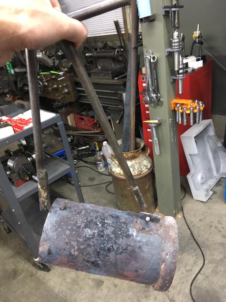
These are from 2001. Before I had a decent camera. I'll go down and take some closeups of the mechanism.
Here's a few I just took
http://www.autoartisans.com/foundry/D8X_5813.JPG
http://www.autoartisans.com/foundry/D8X_5814.JPG
http://www.autoartisans.com/foundry/D8X_5815.JPG
http://www.autoartisans.com/foundry/D8X_5816.JPG
Essentially it's an over center locking mechanism that is forced that way by the top clamp hitting the rim of the crucible. One the thin long handle cross over that center point I don't have to hold it down.
And this was not my idea. It came from one of my metal working friends in Edmonton.
Attachments


Last edited:
Surreal colour. Why is that?Interesting approach using just the single hole at the top. My tangs have shoulders and theoretically the lift part will hook on and then mine will pivot down and hook at the bottom to a loop (Chain link) at the bottom.
View attachment 7934
This is just a trial on a piece of scrap milled with LinuxCNC. The first few inches of the angle would be cut away so that it can clear the sides of the furnace. The one on the right will be the mirror image.
My 6# is lifted with a different type of holder since the furnace body lifts up. I can pick it up and pour from the side. I will make the part that goes around the crucible removable and create a larger one for the #8.
View attachment 7935
Who’s picture are you referring to?
Sent from my iPhone using Tapatalk
Sent from my iPhone using Tapatalk
You mean the blue, silver and black? Black is a handle. Blue is the frame and the silver is high temperature paint. My tongs are done the same way as was the furnace (almost) although I never did finish painting the cart. Too eager to start casting and then 19 years later it hasn't changed.
http://www.autoartisans.com/Furnace1jpg.htm
http://www.autoartisans.com/Furnace1jpg.htm
That was back with small Nikon point and shoot at night and the auto white balance didn't know what to do with it.
Probably closer to this

Probably closer to this
One of the problems with months between the start of a project and then subsequent restarts is I forget what I was doing and worse I often forget the successful approach do doing some of it. Seems like it's relearning every 6 months or 2 years.
For my mill I'm changing over from 2HP cast iron single phase 2HP (1.5kW) to high tech AC Servo (1.8kW). It will allow me to get rid of the intermediate pulley and tension arrangement and switch to just a single pulley and perhaps no belt change since the spindle motor will go from 0 to 3000 RPM and the current setup has a high end speed of 2950 RPM.
I probably could have gone to the local laser cutting place and had them cut some 3/4" and 1/2" plate for some reasonable but outside my budget price. Especially since I can cast it with a few of dollars of natural gas and primer/paint/mdf for the pattern.
Then use the existing CNC conversion to properly mill the parts. Now granted I could set the band saw table and disk sander at 3 degrees for draft along with the sabre saw for the hole. But when there's a CNC router (MACH3 controlled) and AlibreCAD/CAM why not use the tools.
Problem is I haven't used the tools for 6 months and it's the little details that have escaped. The up side is first try is close. The down side is I really couldn't get the draft cut. Almost looks like a backlash issue on the CNC router. Lots of draft on one side but none on the other. Expanding the original drawing by 4% to account for shrinkage worked but it also make the motor mount hole larger rather than smaller. So the motor won't register against the hole.
But the second try will be better.
Attachments


The motor mount plate is 10.5" x 7.375" for the 1.8kW AC Servo. This discussion should probably be on the Mill conversion thread but I thought since I'm casting these parts I figured a series of photos (of the mistakes too) showing conception to pattern to casting was better here. Once the machining starts I'll resume on the G3616 thread.That looks just like my mini mill belt drive conversion mount .... what are the dimensions on it?
The first pattern did not have the draft work out correctly on the outside. And scaling the pattern up by 5% to account for shrinkage made the middle hole way too large to fit the motor flange. So I redid it with more passes to deal with gantry shake and with a smaller hole. Taper on the outside was now correctly created by the CAM software.
Primed and ready for wet sanding and paint. Hopefully casting this weekend.
Primed and ready for wet sanding and paint. Hopefully casting this weekend.
Attachments


I started with this because I found a couple of his build metal shop from scrap books in the local library. I ordered the entire set from him and got started with the gas fired foundry. One of the best things I ever did.
-->Dave Gingery<--
-->Dave Gingery<--
You spend about 98% more time on your patterns than I do....... and the results show! Mighty fine looking blanks!
Gingery was before his time
Sent from my iPad using Tapatalk
Gingery was before his time
Sent from my iPad using Tapatalk
I was woodworking as a hobby before I discovered casting. I must admit I really enjoy making patterns. Even if they are 3D printed and then filled, primed and painted. There's a real sense of accomplishment when the pattern is pulled from the green sand and then again when the casting comes out looking like it should.
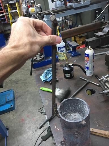
Finally got my pipe crucible lifter/pouring handle finished. So today I had to try it out. Learned I'll have to weld on some T handles in a couple of places to make twisting for pouring under control easier. I can pour by pouring out the opposite side of the handle but I'd have to be standing over the flask and potential blow back is why I like to be off to the side when pouring.
I also need to make an ingot mold that can create 2.5 lb ingots since the small ones for the #6 crucible.
But maybe Friday I can actually pour a casting.
I also need to make an ingot mold that can create 2.5 lb ingots since the small ones for the #6 crucible.
But maybe Friday I can actually pour a casting.


