• Spring 2024 meetup in Calgary - date Saturday, April 20/2024. discussion Please RSVP Here to confirm and get your invitation and the location details. RSVP NOW so organizers can plan to get sufficient food etc. It's Tomorrow Saturday! you can still RSVP until I stop checking my phone tomorrow More info and agenda
  • We are having email/registration problems again. Diagnosis is underway. New users sorry if you are having trouble getting registered. We are exploring different options to get registered. Contact the forum via another member or on facebook if you're stuck. Update -> we think it is fixed. Let us know if not.
  • Spring meet up in Ontario, April 6/2024. NEW LOCATION See Post #31 Discussion AND THE NEW LOCATION

CMT Ursus 250 Repair: 1) Clutch

RobinHood

Ultra Member
Premium Member
Thanks for the tips on HT procedure - well noted.

No, I have not taken the time to contact the folks in Italy yet. I really should, you never know what might come of it... Thanks for reminding me, John.

Too focussed on making do with what I have around (or can get quickly off the shelf).
 

RobinHood

Ultra Member
Premium Member
Thanks for the link Tom. I’ll keep them on the back burner if things don’t pan out.

While i wait for stronger wave spring washers to come in, I’ll push ahead with the bronze bearings in the clutch baskets. They are a right old mess: two spun in the FWD basket (A) and were “welded” to the shaft. The REV basket (B) had one still pressed (and locktited) in and the other was spinning both on the shaft and in the basket bore.

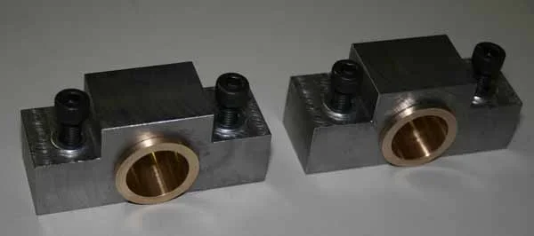
General overview of the parts. Bronze bearings are in front of each basket.
1B1A01BA-E28E-44FE-9DFE-E9EC4A6E3EBB.jpeg

Close-up of the REV basket. You can see the space between the two bearings. It is crucial as that is where the pressurized oil enters through a hole in the bearing journal.
E0B64212-9B6E-4F65-8AB0-B20BE5A981EC.jpeg

And the much worn FWD basket bearings. The required gap between them is completely gone because of wear on the shoulder of the inner half.
3471176F-34AB-4704-8398-A91146A05862.jpeg

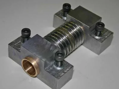
A picture of the clutch drive shaft with the lubrication holes in the journals.
BFAA8122-08A3-48C7-B9E3-85DE35ED16CF.jpeg

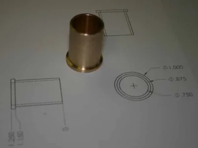
Close-up of one half of the bearing - the shoulder takes up axial thrust. The oil grooves allow lubrication of both the shaft journal and the ball bearing supporting the clutch shaft. (In the pictures above, only the front double row ball bearing is still on the shaft - the rear one had to come off in order to extract the shaft from the HS.
3DF5187A-AF79-452A-B474-56997EBE070D.jpeg

And the very worn inner half - the shoulder is supposed to be 5.0mm!
DD0485A9-E349-4D17-BB43-C2E549D479C0.jpeg

Here the old bearings are in their respective baskets and the “naked“ clutch pack is between them; this set-up was used to determine the required width of each bearing shoulder. (The output gears are also missing off of each basket journal - the locating key ways are visible).
7B770FC0-7BCD-4B2A-93BC-C8FCF0579576.jpeg

My plan is to make the new bearings a proper press fit (no locktite). Then finish-bore to shaft size after. A shoulder protrudes on each end. This is critical, as it sets the end play of the clutch pack. The old ones allowed the clutch pack to slide axially by almost a 1/4”! That would have made for a very sloppy clutch feel.

What size bearing bore would you use to allow a proper oil film lubrication and yet not have excess radial play? I am also expecting the bearings to expand a bit as they warm up. The shaft journals are 27.99mm and 32.99mm respectively.

There is a Figure 6 in the MHB (29th ed, pg 2331) giving a range of about 0.0014“to 0.0042“ operating diameteral clearance for the small journal and about 0.0016” to 0.0045” for the larger one. They also go into an extended calculation of lubricant film thickness. I have too many unknowns and thus can’t complete the math. Hence the question about bore size vs given journal diameter above.
 

PeterT

Ultra Member
Premium Member
Hmmm.. cant contribute anything useful. Split the difference & go in the middle? If you went for the smaller annular gap you could probably lap out a thou if it felt too sticky, which is maybe better than if it was too loose to begin with & will only grow larger with use. But guessing you probably don't want to go back in here anytime soon once its buttoned up. The only remotely close thing I've ever made was bronze bushings for my lathe modified worm gear block. I want to say ID was 0.002" over PF shaft OD because it says 0.750" on 19mm (0.748) shaft. I was aiming for a looser fit because casting alignment of this machine is a bit iffy. It leaves a nice (way) oil film, but its not really loaded like your application.
 

Attachments

  • IMG_6356_edited-1.jpg
    IMG_6356_edited-1.jpg
    26.4 KB · Views: 2
  • IMG_6354_edited-1.jpg
    IMG_6354_edited-1.jpg
    37.4 KB · Views: 3
  • IMG_6352_edited-1.jpg
    IMG_6352_edited-1.jpg
    25 KB · Views: 2

Brent H

Ultra Member
Hey Rudy,

Rule of thumb is 0.001" per inch of shaft diameter - min 0.001" . If you are installing bronze bushings - can you make them out of bearing bronze? as in oil impregnated? Not the sintered ones but standard oil impregnated? I would make for a 0.0015 clearance

The loss of material on the back of the bushing you have in the caliper (picture 6) shows that at least that bushing was rotating in the clutch pack and the front (actual bearing surface) was not doing its job - Perhaps this loss of clearance is impacting the clutch arrangement such that your new spring washers are not able to apply the tension required as the bushing is allowing too much play?

You will need to account for the press fit - probably good with a 0.001 to 0.0015". Looks like the one bushing spun and wore and then plugged off the oil passage, which created further issues?
 

cuslog

Super User
Premium Member
Just a couple thoughts here;
Those clutch packs look an awful lot like clutch packs in an automatic transmission (although probably smaller). I wonder if someone from a transmission shop might be able to help you or have some suggestions ?
I Drag raced for several years, we used to take out the wave washers to get a firmer shift, would mix and match frictions and steels thicknesses to get to a specific stack height.
Some "old school" brake / clutch shops used to re-line friction plates.
 

RobinHood

Ultra Member
Premium Member
@Brent H , I have 932 bearing bronze I was planning on using. I don’t think it is oil impregnated though.

I think you are right on the money with your analysis of why the bearings spun.

Here is my take:
Having worked on the lathe for some time now, the craftsmanship is absolutely outstanding and the fit, finish (except perhaps the original bondo/paint job), and tolerances are out of this world. Like who cylindrically grinds their threading dial shaft and underside of the number face & runs it in bronze bearings? CMT does!

B0AD0FF2-3822-4D28-ACFE-A635E5699681.jpeg

F7E5C171-C8E3-480D-B1F2-419403D0D2AE.jpeg

Anyway, the baskets were turned, heat treated and cylindrically ground. The bearings were made and pressed into the bores. I think they were too loose. They went back and locktited them in. The ID of the bearings were a very close running fit (too tight perhaps in hindsight?). The oil passage inside the clutch shaft is quite large and it would probably take 10-15 seconds for it to fill and build up pressure and thus force the oil through the hole into the bearing. Meanwhile, the shaft is turning at about 1500 rpm. I think the bearings heated up very rapidly during that time - I could see burnt oil residue on the ones that were stuck to the shaft. Over time, the little clearance between journal and bearing got smaller and smaller and then it seized onto the shaft and the bearing started turning in the basket bore. There is no lubrication groove on that side and initially, no oil would get in there. The bearings would wear rapidly. Then they are free running in the bore with now lots of clearance (there is over 1.5mm diametral clearance in the old bearings!). Some oil then splashed in that gap and the wear rate decreased dramatically. 3 out of 4 bearing halves did that. There was only one that was still pressed into the REV basket bore. It still had lots of wear on the journal face, because its mate was spinning both on the journal and inside the basket bore. So it was overloaded because it did the job for two. Since it is the REV side - which does not see that much use - it “survived“ until now.


The loss of material on the back of the bushing you have in the caliper (picture 6) shows that at least that bushing was rotating in the clutch pack and the front (actual bearing surface) was not doing its job.

Yes, it was stuck to the journal on the shaft (thus turning with the shaft) and the basket was spinning on it. It has over 1.5mm of clearance worn on the wrong diameter (its OD).

Perhaps this loss of clearance is impacting the clutch arrangement such that your new spring washers are not able to apply the tension required as the bushing is allowing too much play?

I was looking at that and was wondering if there was any correlation. Here is the conclusion I have reached so far: the clutch pack/cartridge is a separate, self contained unit. It is a close sliding fit on the shaft and is prevented from rotating with a key. It can only slide axially, the amount of end play being controlled by the bearing shoulder widths - which are: 4mm, 5mm, 5mm, and 4mm (left to right for each of the 4 bearing halves —> giving a theoretical end play of 0mm). The clutch plates are held constrained by a big retaining ring on each outside (red arrow shows the ring groove - other side shows snap ring and pressure plate installed; the pack is totally symmetrical) and the adjuster ring for each side located towards the center of the pack. The adjuster ring bottoms out against a shoulder (yellow arrow). So the spring issue is as self contained problem, not influenced by the endplay of the pack. The end play manifests itself by more free travel of the clutch lever before engagement takes place as the clutch collar pushes the pack axially on the shaft until it bottoms out on the bearing shoulder.

CD73D2EC-33AC-4904-88F5-60482C96D6B7.jpeg
 

RobinHood

Ultra Member
Premium Member
Just a couple thoughts here;
Those clutch packs look an awful lot like clutch packs in an automatic transmission (although probably smaller). I wonder if someone from a transmission shop might be able to help you or have some suggestions ?
I Drag raced for several years, we used to take out the wave washers to get a firmer shift, would mix and match frictions and steels thicknesses to get to a specific stack height.
Some "old school" brake / clutch shops used to re-line friction plates.

Thanks for your tips!

I was looking into automotive replacements as well. Seems that the diameters are quite different from what I have found so far. The plates OD are just under 4” and the ID 2.25”. The closest I have found were some motorcycle clutches as far as overall size is concerned. Biggest difference is that this clutch does not have the traditional “frictions & steels” - both drivers and drivens are made from the same spring steel material. Just the shape is different and the ground grooves.

According to a supplier in Italy, they have whole clutch pack assemblies. I have not yet asked them if they have this particular one and how much it would cost. I think it won’t be cheap, judging by the price of the manual for the lathe I purchased from them: $400+ (it is not even complete - nor does it give the parts description, only the parts diagram...), but it has helped me with disassembly, so it was still worth the high price.
 

Brent H

Ultra Member
So then Rudy, The actual "clutch assembly" is not so much a clutch one would engage to run the feed but more of a friction fit shaft coupling that will act to release the feed shaft in the event of an unforeseen stoppage thus preventing catastrophic failure of the shaft and possibly apron gearing etc. ?

the adjuster ring for each side located towards the center of the pack. The adjuster ring bottoms out against a shoulder (yellow arrow). So the spring issue is as self contained problem, not influenced by the endplay of the pack.

Is that ring bottoming out before you are able to increase tension on the spring pack? It would seem to me that provided you compensated for the broken springs with the ones you made (basically to eat up the missing space), you should be able to still adjust that tension (like the drag on a fishing reel) from a point of too much slippage to a point of no slippage and being to tight? Your adjustment would be at the point where you achieve a solid feed without slippage under good load and the clutch would still yield at a stop.

That being said, if a previous owner had set up for multiple parts and applied a fixed stop to the apron and used that as a means of controlling the feed : it would account for heating up that spring pack, loading the bushings and the wear on the springs that broke. I noticed your previous pictures that the crowns of the wavy washers appeared like they had spun a few times.
 

RobinHood

Ultra Member
Premium Member
So then Rudy, The actual "clutch assembly" is not so much a clutch one would engage to run the feed but more of a friction fit shaft coupling that will act to release the feed shaft in the event of an unforeseen stoppage thus preventing catastrophic failure of the shaft and possibly apron gearing etc. ?

Well, sort of, but not quite. The lathe is a “clutched lathe” like a Colchester Master, Triumph, Mascot, etc, or a the Monarchs that Keith Rucker and Adam Booth run. You start the electric motor, select the gear and then engage the clutch to get the spindle moving. All the power flows through that clutch.

The lathe has a secondary feed shaft protection device. I’ll report on that when I go into more detail of the other features of this lathe.

Is that ring bottoming out before you are able to increase tension on the spring pack?

Yes, it is if I remove the broken parts. That is the main reason I need to replace the spring washers. I could make a spacer for the broken items and remove, say, 2 drivers and two driven plates. That reduces the torque transmitting capability of the clutch assembly and would stress the remaining components more - accelerating wear - as the pack will be down to 6 drive plates and 5 driven plates (from 8 and 7, respectively).

Lathe clutches of this type are “normally open” - no power is transmitted, as compared to a motorcycle or car with a manual gearbox, whose clutches are “normally closed”. This means that it is vital for the longevity of the device that the plates separate and do not drag when the clutch is not engaged but still turning as the electric motor is still turning the input shaft.

That being said, if a previous owner had set up for multiple parts and applied a fixed stop to the apron and used that as a means of controlling the feed
The lathe can actually be used in the way you suggest. It is a different, ramp type of mechanism they use for that. I will explain when I talk more about the apron features in another post.

I noticed your previous pictures that the crowns of the wavy washers appeared like they had spun a few times.
Yes, good observation. I did see that as well. I think it was because the clutch was set too tight because they no longer had the adjustment after the springs broke. So they were dragged along by driven plate - which is normally not moving when the clutch is open. The rubbing would have been against the driver plate.
 

YotaBota

Mike
Premium Member
This is way above my expertise but you make it look easy and it's very interesting to watch your progress.
I wonder if the company has a "rebuild kit" or if they have rebuilds for exchange (and money). It would take away the rebuilding experience but would get it done. I don't blame you for being gun shy about asking the OEM for parts, especially at $400 for a manual.
 

PeterT

Ultra Member
Premium Member
Robinhood do you have a way to quantify the spring force of old & new? Like with a test indicator & press step in increments & record pressure (force). That might help you zero in on what you need by interpolating the thicknesses you have & what might be available even though not identical
 

RobinHood

Ultra Member
Premium Member
Not yet. Looks like I have to come up with a way to measure the springs if the new, stiffer, ones don’t get me there. They are due to arrive later this week...
I do have an idea of how to make a set-up for a comparative deflection measurement.
 

cuslog

Super User
Premium Member
Robinhood do you have a way to quantify the spring force of old & new? Like with a test indicator & press step in increments & record pressure (force). That might help you zero in on what you need by interpolating the thicknesses you have & what might be available even though not identical

I've done just that with checking spring rates on springs for coil-over shocks. Used a bathroom scale on my mill table, spring on top, compress the spring 1", read the scale. I checked some used, some new (all with rating tags on them). Was actually surprised at how close the readings were to what the tag said. Kind of crude, I know but actually gave a pretty good idea of spring rates.
This is a smaller scale application but maybe a kitchen scale on the mill table and compress just a few thousandths ?
 

RobinHood

Ultra Member
Premium Member
This is a smaller scale application but maybe a kitchen scale on the mill table and compress just a few thousandths ?

That is an excellent idea for a set-up! Thanks for sharing.

I was going to use angle plates bolted together so that I can mount a dial indicator from below. Have the probe stick up through a slot. Place a spring centered on the probe. Put a plate on top of the spring. Start loading with ziplock baggies fillet with sand. Measure compression with each additional baggie. Compare OEM to new to see what the difference is. I don’t think I really need to know how much each baggie weighs, as long as I use the same ones for each test. I could always weigh the baggies afterwards if I wanted to get quantitative numbers I guess.
 

RobinHood

Ultra Member
Premium Member
The bushings are done, pressed in and ready for final machining. Messed up one - it was perfect based on the drawing measurement, except the measurement on the drawing was off by 0.50mm. Of course it was too small - no way to salvage it. Should have used the guess-o-meter for a bozo check after measuring the bore of the basket lathe at night... oh well.

That 932 bearing bronze turns nicely, even used power feed to part it off. Here’s the last one.
F307F229-030A-4F78-8C74-EE3F7F89C729.jpeg

Had to remember the press on the gears onto the basket first as they a captive behind the outer bushing’s shoulder.
E2C22A03-62C8-4A71-A246-7FAB195E7A7A.jpeg

Both ready for the 4J to size the bore and the outside bearing shoulder. It has a little step about halfway up the side that butts up against a shoulder on the clutch shaft on the REV side (B basket) and the inner race of the shaft support ball bearing on the FWD side (A)..
5FDE436E-5559-4547-BDFC-A9A0F75E6A32.jpeg

The last op will be to broach the oil grooves in the bushings. I’ll do that on the Bridgeport using the quill and a tool that I have made and already used for an oil lubricated bushing in the apron which was worn.
 

PeterT

Ultra Member
Premium Member
The weigh scale method is exactly how I checked some baby springs. I just put an dial indicator on the drill press quill with a dowel pin gripped in the chuck. Increment the Z amount in steps, recording scale readings along the way. Obviously your scale has to accommodate the spring force over test range but you may not have to go to max compression if you plot it up on graph paper & get an idea of average slope extrapolation (spring rate). Then compare to your other spring. Actually you could even stack your 2 dissimilar ones to get some idea of the blend, but it may not be indicative of different counts of them in a cluster. I'd be surprised if they varied much from manufacturers specs but maybe if there was some damage they got exposed to different force. I'm actually not sure if wave springs have a maximum deflection 9compression) if they go into kind of a deformation mode.
 
Top