-
Scam Alert. Members are reminded to NOT send money to buy anything. Don't buy things remote and have it shipped - go get it yourself, pay in person, and take your equipment with you. Scammers have burned people on this forum. Urgency, secrecy, excuses, selling for friend, newish members, FUD, are RED FLAGS. A video conference call is not adequate assurance. Face to face interactions are required. Please report suspicions to the forum admins. Stay Safe - anyone can get scammed.
-
Several Regions have held meetups already, but others are being planned or are evaluating the interest. The Calgary Area Meetup is set for Saturday July 12th at 10am. The signup thread is here! Arbutus has also explored interest in a Fraser Valley meetup but it seems members either missed his thread or had other plans. Let him know if you are interested in a meetup later in the year by posting here! Slowpoke is trying to pull together an Ottawa area meetup later this summer. No date has been selected yet, so let him know if you are interested here! We are not aware of any other meetups being planned this year. If you are interested in doing something in your area, let everyone know and make it happen! Meetups are a great way to make new machining friends and get hands on help in your area. Don’t be shy, sign up and come, or plan your own meetup!
You are using an out of date browser. It may not display this or other websites correctly.
You should upgrade or use an alternative browser.
You should upgrade or use an alternative browser.
C'ADventures
- Thread starter David
- Start date
- Status
- Not open for further replies.
Xyphota
Ultra Member
I only have experience with Fusion and SolidWorks so far, and between the two, Fusion is much less user friendly. My biggest gripe is how much it relies on the user to click on things which sounds stupid, but if you know, you know LOL.
It also hides lots of the relationships in sketches by default, so you can't see which relationships are applied to an element unless you hover your mouse over it. And then, if you have an element that has several of the same relationships (i.e. a line has a parallel relationship with several other lines), it is unclear which relationship belongs to which element. This makes editing sketches a huge pain. And don't get me started on assemblies... Lots to grumble about in fusion lol. Although, Fusion CAM is more user friendly than Solidworks.
It also hides lots of the relationships in sketches by default, so you can't see which relationships are applied to an element unless you hover your mouse over it. And then, if you have an element that has several of the same relationships (i.e. a line has a parallel relationship with several other lines), it is unclear which relationship belongs to which element. This makes editing sketches a huge pain. And don't get me started on assemblies... Lots to grumble about in fusion lol. Although, Fusion CAM is more user friendly than Solidworks.
The fundamental problem with Fusion 360 is that it hides so many "options" under deeply nested and hidden menus. If you don't know the feature exists (oh, yes, it probably does), and you can't figure out its name you simply can't find it. Then you're stuck in slow-paced useless training videos.
Like most pro tools, there's an expectation of significant investment to become competent instead of a being able to muddle your way through using the various on-screen prompts and menus.
[Never ask to drive my text editor, you probably can't without significant seemingly unrelated experience in Unix shell work, or a 30 day deep dive into it].
I have the hobbyist vesrsion of Fusion on my desktop machine and now that I'm a little bit conversant in 2D and 3D I'm curious to try Fusion again to see if I can make it work. I run into lots of models built and shared in f3d file format that I'd like to be able to work with them more easily.
Xyphota
Ultra Member
Oh one other thing that is actively anti-user friendly about fusion that David just reminded me of, if you are opening non-native file types in Fusion 360, you have to manually toggle on "Capture Design History" for every new part, before you start making any changes to the part. There is a setting that supposedly turns it on by default, but this setting does not apply to non-native files???? Without "Capture Design History" enabled, you can't roll back your changes to parts. So if you've spent an hour skillfully building sketches and features that you want to be flexible, and then decide you want to change a dimension on an earlier feature but forgot to turn on capture design history, you are just boned. You can either ctrl-Z your way back to it, or just start over.
Maybe if I mentioned my current job uses Fusion as the defacto CAD software in my career advice thread, people would have been more understanding of me wanting to do something else 😉
Maybe if I mentioned my current job uses Fusion as the defacto CAD software in my career advice thread, people would have been more understanding of me wanting to do something else 😉
BTW, I know Alibre Design changed their User Interface away from the one I'm comfortable with when they released Revision 26 which is the revision of Alibre Atom that @David_R8 is using. Suddenly the ICONs along the top are larger and you can't make them smaller so they take up more of the drawing screen. Not a lot but annoying. And the owner of Alibre 'claims' it couldn't be helped. I don't believe him. But I think he's trying to make Alibre more Fusion360 like in the user interface.
What the two screen shots show is his 'changes' have impacted the amount of usable space for the drawing and the top menu bar is now forced to that stupid dark background with white text which my old eyes have more trouble reading. Again. It's not a lot but enough that if I wanted more on the upper tool bar I'd have to have two lines and lose even more area.
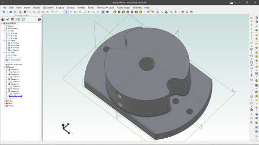
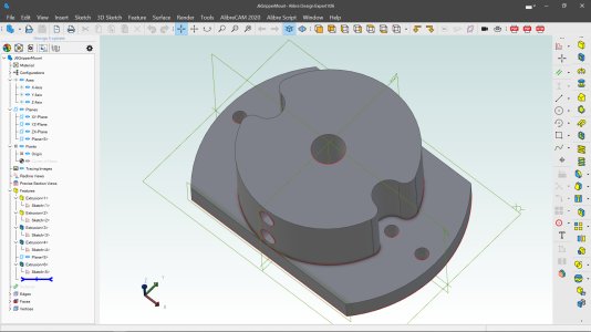
What the two screen shots show is his 'changes' have impacted the amount of usable space for the drawing and the top menu bar is now forced to that stupid dark background with white text which my old eyes have more trouble reading. Again. It's not a lot but enough that if I wanted more on the upper tool bar I'd have to have two lines and lose even more area.


I always start models in fusion with a 2d sketch, in my limited cad experiance I thought that's how everyone did it
hit create sketch in the top right and then click on the plane, now your sketching, all the sketch tools will appear in the tool bar
You make it sound soooooo easy. I think I must be missing something really simple.
How do I make a simple 2D rectangle sketch from 0,0 to 0,2 to 2,2 to 2,0 and then complete the square back to 0,0?
And then how do I pull that up in 3D to a full 2x2x2 cube?
Two very simple tasks. Or at least I have to believe they should be.
Its funny, once I have that simple solid block I have been generally able to make whatever I want out of it. Almost like machining a part from a block. Perhaps not optimally, but still acceptably.
Use the rectangle tool to draw the square. It will/should allow you to enter the dimensions for the sides.You make it sound soooooo easy. I think I must be missing something really simple.
How do I make a simple 2D rectangle sketch from 0,0 to 0,2 to 2,2 to 2,0 and then complete the square back to 0,0?
And then how do I pull that up in 3D to a full 2x2x2 cube?
Two very simple tasks. Or at least I have to believe they should be.
Its funny, once I have that simple solid block I have been generally able to make whatever I want out of it. Almost like machining a part from a block. Perhaps not optimally, but still acceptably.
Switch back to 3D and extrude the square.
Presto a lovely 2" x2" x 5" block of 12L14 😀
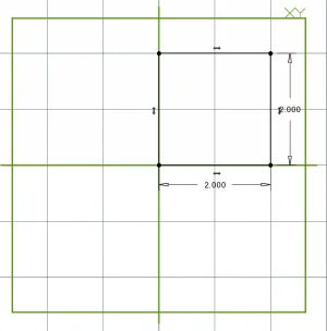
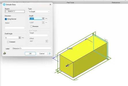
Last edited:
Start with the XY plane as the drawing surface. Then select the draw rectangle anchored on the center instead of corner. Drop it on the origin of the sketch and then tab between fields to set the dimension. Hit ENTER to save. Then as David said, extrude to a height in either the positive or negative direction.
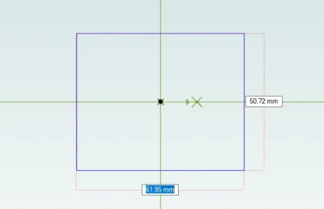

Now let's put a screw hole in the side.
Select the side and click on the 2D draw ICON I have circled on the side. Or however you have your user interface set up.
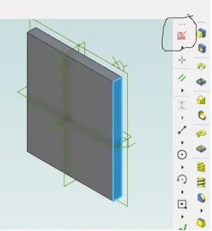
Draw a circle on the side which has now been presented as a flat 2D surface and set the diameter to 2.0mm
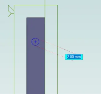
Then select extrude cut and drill the hole.
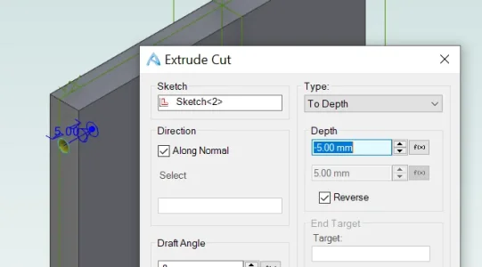
And so on.
Select the side and click on the 2D draw ICON I have circled on the side. Or however you have your user interface set up.

Draw a circle on the side which has now been presented as a flat 2D surface and set the diameter to 2.0mm

Then select extrude cut and drill the hole.

And so on.
Oops. Forgot to position the hole in the center of the edge.
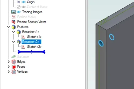
Not a problem. Select Sketch<2> (which you can rename to be end mount hole if you want). Right click on that and you are again presented with the drawing surface.
Now we could just select the dimension tool and the center of the hole and the edge. Then enter in what we know is 2.5mm for the centerline of our 5mm thick part.
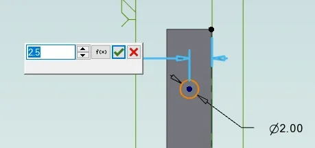
That's the easy way but this is what they call parametric CAD. There's a more fun way to do this. I can click on the f(x) button instead and get this dialog. There are ways to rename and make this more human friendly but for now we know that we extruded the first part to be 5mm thick so we use half of that to position the hole from the side.
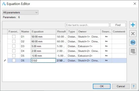
The hole is still 2.5mm from the edge.
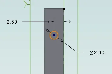
But now thinking about it I really want this piece to be 1/2" thick because that's a piece I have lying around. I'm working in metric units right?
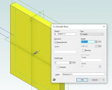
Right click on the original thickness extrusion.
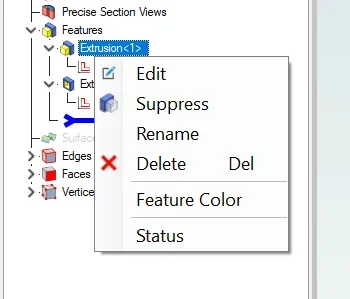
And enter the 0.5" with the double quote signifying inches instead of the default mm.
Save and edit the 2D Sketch again and see how the hole stays in the middle and our part to which I added a dimension so I can see the width (but can't change it here) now has the hole still centered.
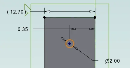
I could have not used the function and always have it 2.5mm from one side.

Not a problem. Select Sketch<2> (which you can rename to be end mount hole if you want). Right click on that and you are again presented with the drawing surface.
Now we could just select the dimension tool and the center of the hole and the edge. Then enter in what we know is 2.5mm for the centerline of our 5mm thick part.

That's the easy way but this is what they call parametric CAD. There's a more fun way to do this. I can click on the f(x) button instead and get this dialog. There are ways to rename and make this more human friendly but for now we know that we extruded the first part to be 5mm thick so we use half of that to position the hole from the side.

The hole is still 2.5mm from the edge.

But now thinking about it I really want this piece to be 1/2" thick because that's a piece I have lying around. I'm working in metric units right?
Right click on the original thickness extrusion.

And enter the 0.5" with the double quote signifying inches instead of the default mm.
Save and edit the 2D Sketch again and see how the hole stays in the middle and our part to which I added a dimension so I can see the width (but can't change it here) now has the hole still centered.

I could have not used the function and always have it 2.5mm from one side.
Oh and BTW, I still have my HP calculator and use it daily along with the HP calculator app on my phone.
Also just started playing around with the FORTH programming language this week which is also RPN based.
Also just started playing around with the FORTH programming language this week which is also RPN based.
Be careful! FORTH is a cult!Also just started playing around with the FORTH programming language this week
For me things are just starting to click in Fusion 360 as I now have a bit of a handle with offset sketch planes.
Hmmm.Be careful! FORTH is a cult!
Code:
***** FORTHWIN *****
thanks to RuFIG  www.forth.org.ru Started by A.Cherezov
 Build 004 at 23.May.2019

>S" c:\forthwin\demos\cult.f" INCLUDED
 Ok
>CULT
Warning! Warning! Will Robinson! FORTH is a CULT!
 Ok
>Matt-Aburg
Ultra Member
For me, I only used sketches long time ago. Most objects are started with primitives, such as Cube, Cone, Cylinder, etc. From there I will use move face, draft, split body, unite, etc. I usually kill the parameters so there is no history. If you move any dumb solid, the default location for from point will always be center of mass.You make it sound soooooo easy. I think I must be missing something really simple.
How do I make a simple 2D rectangle sketch from 0,0 to 0,2 to 2,2 to 2,0 and then complete the square back to 0,0?
And then how do I pull that up in 3D to a full 2x2x2 cube?
Two very simple tasks. Or at least I have to believe they should be.
Its funny, once I have that simple solid block I have been generally able to make whatever I want out of it. Almost like machining a part from a block. Perhaps not optimally, but still acceptably.
In Mold design, we would create the partingline on layer 26 (no fillets or history). live-link this to layer 27 for core, and 28 for cavity. These subsequent layers would have all history of fillets, clearances etc. live. Ideally if you change anything on layer 26, it will roll your changes through layer 27 and 28 automagically.
After the partingline is complete, or even before... the layers 27 and 28 are wave-linked directly into the core and cavity shoe. The blocks are then trimmed with these sheet bodies.
Hierarchy for mold design goes as follows.
Original part renamed with *.*-CTM (for employer name).
Original data copied from to layer 255.
DFMA changes made to original part on layer 1 keeping history.
Part wave-linked to shrink part, where we expand the part (history is live).
Shrink part wave-linked to molding, which is then moved to mold position (in assembly). Core and cavity split done here onto layer 27 and 28.
Molding layers 27 and 28 are wave-linked into partingline file and sew to their respective sheet bodies.
Parting-line layer 27 wave-linked to core shoe.
Partingline layer 28 wave-linked to cavity shoe.
And it continues... but history is only kept where needed. On the shoes for example, it is live, all screws, ejector pins, mechanisms etc. are live cuts that can be rolled back, or updated from the parent part. We NEVER do changes to the partingline in the core shoe for example. Doing so, is guaranteed to cause failure later if you were to update any parent file.
Last edited:
For sure SolidWorks is the Sketch-to-Solid workflow, which I naively assumed was pretty universal in 3D modelers. Whether the sketch occurs on a primary plane or constructed plane or any surface plane or 3D space is up to you. Once a sketch is made, now you have the arsenal of 'feature' tools - extrude, cut, revolve, loft... and the sketch is associated to that particular feature in the history tree. My exposure to other cad modelers is pretty limited, but from the odd tutorial video of F360, Inventor, FreeCad, others along the way I've forgot - I got the vibe it was similar in this regard. I ran Rhino like a dozen years ago, even it worked that way. Although I recall you could also start from a solid 'primitive' & kind of work backwards & manipulate it into something different. That mode never struck me as useful or efficient for the type of work I did. I'm not talking sub-D modelling, that's different again.I always start models in fusion with a 2d sketch, in my limited cad experience I thought that's how everyone did it
hit create sketch in the top right and then click on the plane, now your sketching, all the sketch tools will appear in the tool bar
So if you've spent an hour skillfully building sketches and features that you want to be flexible, and then decide you want to change a dimension on an earlier feature but forgot to turn on capture design history,
You can do this in fusion, I don't remember what the feature is called but you assign your dimension to an assigned variable, then later you can change that variable at will without going back and forth and it will do all the re-work, no going in the history, no re-sketching things.
need your hole to be 4mm instead of 2, change the variable and the software does the rest
- Status
- Not open for further replies.

