• Scam Alert. Members are reminded to NOT send money to buy anything. Don't buy things remote and have it shipped - go get it yourself, pay in person, and take your equipment with you. Scammers have burned people on this forum. Urgency, secrecy, excuses, selling for friend, newish members, FUD, are RED FLAGS. A video conference call is not adequate assurance. Face to face interactions are required. Please report suspicions to the forum admins. Stay Safe - anyone can get scammed.

Building SSQA for tractor loader from scratch

Now that summer busy season has settled down.....I can get back to some projects. Since buying the brackets they've done a pretty good job of holding my floor down, and my taken apart for paint belt grinder has been spread all over holding everything else down for the past few months. That's done, reassembled, and finished now (finished last week/weekend, still working on video and build thread), so it's time to get back on this as I need it before the snow flies....

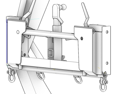
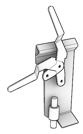
I flipped the levers around from how they shipped, then got to measuring and modeling only what I needed. I had to cut off the bent up stop tab as it interferes with operation. The loader attachment pin plate will provide the overcenter stop in the other direction now. I don't really like how they fit, but since I've only got the import brackets, and an import plate, I don't really know which one needs modifying (think it's a bit of both).....I'll wait until I buy some more attachments to figure it out....
1792928053762.png

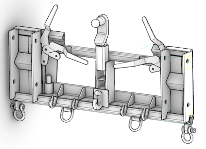
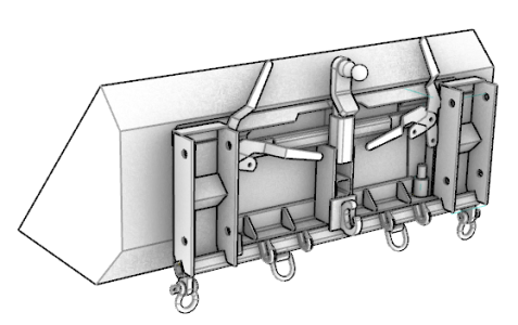
Then I basically started from scratch and redesigned everything to the point I'm at right here, finishing up this morning. I have left room for hydraulic or electric actuator operated locking arms in the future, but for now it's the good ol armstrong operation. A front crank mount hydraulic pump and expanded hydraulic controls are a planned upgrade to the tractor next year, so I'll revisit that when I get there.....
1792928012984.png
1792928752677.png
1792928790512.png


I had to move the pin location relative to the existing bucket up 2", and back 1.5" to give me just enough clearance to make everything fit, while not having excessive overhang. The loader arms being wider than the std ssqa made this considerably more difficult to package tightly.....but not impossible. I lose a bit of dumping height too, but I'm not filling dump trucks here....

I wanted the bracket to be a useful permanent "attachment" in and of itself, so there are a good assortment of lifting options built in, from 5/16" & 3/8" grab hooks, D rings, and some lugs for 3/4" shackles on the ends directly below the pins for my log tongs. There's enough clearance that the shackles can stay on and not interfere with bucket duties. There is a weld on 2T lifting hook dead center for bridle picks, and some 2" receiver tubing pointing forward, and one straight up where a hitch can be left installed so I can simply move trailers by tilting down. I'll probably pad the lifting hooks instead of welding directly to the cross tube as shown when I get to building it.

Pic below is the loader arms at the full range of motion of 123*. The 2" cross tube at the bottom is in the same position as the travel stops currently on the bucket, so I retain that and I won't jack up my cylinders.....The stop at full curl is the cyl cross tube mount itself.
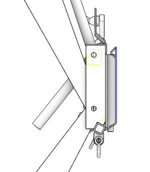
1792928476498.png
Rhino says there's about 700 Cubic inches of steel there, so roughly 200lbs. Cuts into my lifting capacity a bit, but not really since I don't need a bucket or separate attachment to pick stuff, and since most of the pick points are inline with the pins i'll gain some there, not to mention better visibility. The only thing it really hurts is my capacity with forks, but not too bad. The convenience of even HAVING forks on the front is a good trade off.

I think i've covered all my bases here, and have tried to design this in a way that I can make it with stuff and stock I already have on hand. I'm only out of pocket for the quick attach plates, weld on grab hooks, lifting hook, and some d rings, but since I already bought those months ago when starting this project and forgot what I paid for them, they're now free and don't count 😀. I'll be reusing the bucket mounting plates and pins, but aside from that the rest is just some 2x2x1/4" tubing, 3/8" flatbar, and some 3x3x3/8" angle from my stock market.

Hopefully I'll get started this week as I'm back in tradeschool for my last block and have a very favourable schedule this time so I should be able to knock this out pretty quick. But we all know how that goes..... Gotta squeeze one more round of golf in this afternoon though....
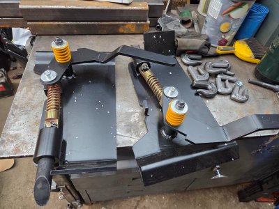
 
I don't really know which one needs modifying (think it's a bit of both).....I'll wait until I buy some more attachments to figure it out....

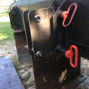
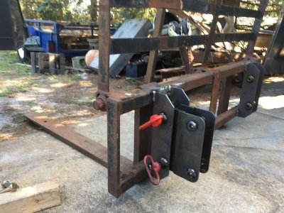
I found that the levers as they ship are prone to popping up and releasing thee retention pin, then when you drag the forks they're prone to semi-detaching and then jamming in an unlevel position.

Ask me how I know.

We're going to add a chain to hold the two levels together in the locked position
 
I found that the levers as they ship are prone to popping up and releasing thee retention pin, then when you drag the forks they're prone to semi-detaching and then jamming in an unlevel position.

Ask me how I know.

We're going to add a chain to hold the two levels together in the locked position
Or put a hydraulic cylinder between them, add a valve and a few more hoses and change from the seat..... my skidsteer is this way and I must say, it's nice. 😉
 
I found that the levers as they ship are prone to popping up and releasing thee retention pin, then when you drag the forks they're prone to semi-detaching and then jamming in an unlevel position.

Ask me how I know.

We're going to add a chain to hold the two levels together in the locked position
Good to know. Something I'll keep an eye out for. As Don said, i'll eventually control it with a cylinder and not have to worry, but until then I'll probably lose a bucket or two lol.
 
Turns out that that 3x3x3/8" angle I designed around (and was sure I had a few sticks left in the barn) was actually 4x4x5/16"....Must have used all the 3x3 for something else and forgot about it. Oh well, not much changes in the design as a consequence and miraculously all those engineering calculations that I put into this stayed the exact same /s 😉.....If anything, it just got a bit lighter as the 15" sections get cut down to 2x3 anyway. Might get to that later tonight but probably not.

20261027_163239.jpg
 
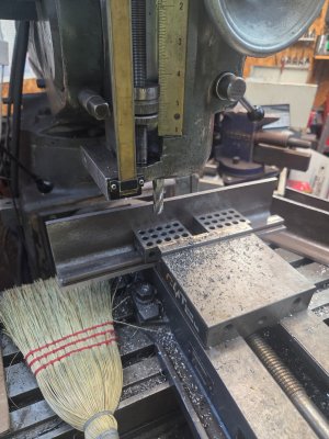
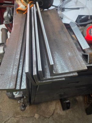
So...I ended up machining those angles down to the correct leg lengths the other day as per my design and called it a day.

20261031_150721.jpg
20261031_154653.jpg

Feeling pretty good about my progress I called it a day and started browsing marketplace as one does.....Then it hit me immediately while looking at an add for quick attach forks......

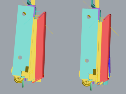
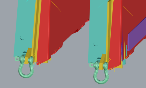
Some quick attach plate sides follow the side angle from top to bottom, and some have side plates parallel to the front plate. Something I didn't consider when designing mine. The nature of my design having the loader arms wider than the entire bracket means that I need that clearance if I'm ever going to use a commercial made attachment made that way without modifying. Not a huge deal I have a grinder, but a bigger deal if I ever need to borrow, or rent something. Small, problem, but a problem I can solve right now very easily despite already making the pieces that are now non reusable.......

Left is new fix, simply rotating loader side 3*. Right is old Parrallel way.
1794176268174.png

As you can see below on the right, if I left it the old way, I'd have interference with any commercial made attachment with tapered sides.

1794176652693.png

I also didn't really like my cross members, and other design details so I went back to the drawing board...(still at the drawing board for some), but I've got enough dont on the side that I can proceed forward with remaking those connector plates. This time instead of using angle, I'm using two flat bars machining with the angle, welded to a flat plate. same/same in the end, just a different way to get there with material on hand.

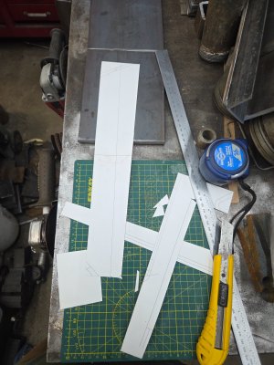
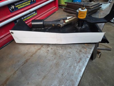
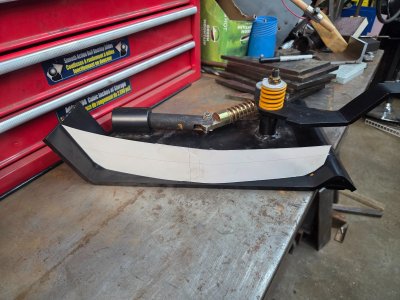
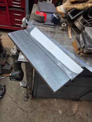
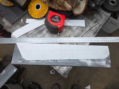
First step was to print off a template from the design, then cut it out and glue it together (15" long), then trace the actual angle cuts from the purchased bracket
20261108_164435.jpg
20261108_165603.jpg
20261108_165844.jpg


I had to laugh today as Watch wes work posted a video of building the same thing for his skid steer. I watched it while doing some cad on this, and giving my back a break, and had to laugh the whole time about the frustration he was having, same with me about building one of these......I sure wish I had a laser and press brake to make mine though. Nice tools. But card stock templates, and bandsaws work too.....

 
After dinner I cut the new parts from 3/8" flat bar. About the last thing I feel like doing right now is hunching over the bandsaw in vertical mode , so I'll leave that for another day. I'll tack them all together after roughing, then machine as one, so they're all the exact same.
20261108_195932.jpg
20261108_195101.jpg

Time to finish designing the rest of it. Again.....
 
Back
Top