• Spring 2024 meetup in Calgary - date Saturday, April 20/2024. discussion Please RSVP Here to confirm and get your invitation and the location details. RSVP NOW so organizers can plan to get sufficient food etc. It's Tomorrow Saturday! you can still RSVP until I stop checking my phone tomorrow More info and agenda
  • We are having email/registration problems again. Diagnosis is underway. New users sorry if you are having trouble getting registered. We are exploring different options to get registered. Contact the forum via another member or on facebook if you're stuck. Update -> we think it is fixed. Let us know if not.
  • Spring meet up in Ontario, April 6/2024. NEW LOCATION See Post #31 Discussion AND THE NEW LOCATION

Bridgeport Mill Tachometer

whydontu

I Tried, It Broke
Premium Member
Sounds great! I'm not sure how your system picks up a paint stripe though. My Quill nut moves up and down about 6 inches. And most of that is buried inside the mill head.

Yes, I agree that swarf and magnets don't mix very well. Yet another reason to rule out that solution.

If I end up going with an optical sensor system, I'll try to avoid IR.

Boy, you do like Arduino don't you!

If I do end up going that way, I'll get back to you and take you up on your offer.

A $5 microcontroller with a USB port, a dozen digital i/o, four analog in, four PWM out, UART, I2C, 32k EEPROM? What’s not to like? All support circuitry is on the board. Plug-n-play.

Only snag with the tach is it tops out about 1500 RPM. No big deal, I’m usually spinning cutters no higher than 1000 RPM.

My mill has a big washer attached to the top of the drive gear that rotates the quill. Busy Bee CT129, part #206. I took a plastic cap from a can of spray paint and painted a couple of white stripes. Bolted the cap to the washer, aimed the IR sensor at the stripes.


3D2BCD70-9FFE-47D5-8360-8CD8AE0AD664.jpeg
 

Susquatch

Ultra Member
Administrator
Moderator
Premium Member
Not a Bridgeport but close enough .......... I ended up dismantling the head to install a hall effect sensor and magnet.........

The tach was a Mach Tach kit that was commercially available a few years ago. The developer is now making the information and files available through Thingiverse.

No worries. One of my mills is a Hartford too. I really like it. You are right, the differences really are minor.

No worries on the kit. I have found lots of hall effect kits like that on Ali, Amazon, and E-Bay. I have even found a few DROs with hall effect based tachs built right in.

I like your control box. My motor has a mounting flange on one side that looks dumb just sitting there with nothing on it. So I had planned to mount my control box there. But I had planned to add a DRO in the next while, so what you did makes sense.

For now, my issues are all with where and how to mount the sensor.

I like your idea of picking up off the spindle side of the bull gear assembly. But I'm thinking it might be possible to use the teeth themselves directly instead of a magnet. Many modern car engines have a sensor that picks up the teeth on the starter ring gear to know exactly where the crankshaft is at any point in time.

Might be a great application for an Arduino too......
 

Susquatch

Ultra Member
Administrator
Moderator
Premium Member
Only snag with the tach is it tops out about 1500 RPM. No big deal, I’m usually spinning cutters no higher than 1000 RPM.

My mill has a big washer attached to the top of the drive gear that rotates the quill. Busy Bee CT129, part #206.

Part 206 looks like a gear to me. But I get the idea now. I had imagined a big long vertical stripe on the spindle not a horizontal one on a washer or gear.

IIs your IR sensor a two part (emitter/receiver)?

Why does it top out at 1500? Is that a speed limitation of the Arduino? If so, I would think they would have a faster version available too.....

I sort of like the idea of counting teeth (have to research that more)....... But that would need even more speed...... Even so, those microcontroller things are WAY faster than us.
 

CWelkie

Active Member
I like your idea of picking up off the spindle side of the bull gear assembly. But I'm thinking it might be possible to use the teeth themselves directly instead of a magnet. Many modern car engines have a sensor that picks up the teeth on the starter ring gear to know exactly where the crankshaft is at any point in time.

One optional input for a Mach Tach option was/is a gear tooth sensor. The application including a housing and circuit diagram can be found here:
https://www.thingiverse.com/thing:1463559
Perhaps this information will help in your quest.
 

Susquatch

Ultra Member
Administrator
Moderator
Premium Member
One optional input for a Mach Tach option was/is a gear tooth sensor. The application including a housing and circuit diagram can be found here:
https://www.thingiverse.com/thing:1463559
Perhaps this information will help in your quest.

Here is a typical automotive tooth sensor. $20 on Amazon. Even cheaper at a junk yard. The dots at the bottom of the right image (number 1) is a cross section of the coil winding.

Crankshaft_sensor.png
 

whydontu

I Tried, It Broke
Premium Member
Photos.

Tachometer, simple plastic box. Held on to the mill control panel with a magnet from a trashed disk drive. Simple and cheap and I can move it when needed (when I'm trying new software).

Sensor is also simple. The disc on the drive collar is just a flat metal plate with a bunch of holes. The original tach setup was a sensor and light pair shining through the disc, counting holes. This tach is long gone, previous mill owner was attempting to convert the mill to CNC and he trashed all of the electronics.

New sensor is a $3 IR card and a plastic cap, painted black, with a white stripe. You can see in the photos that a green LED light comes on when the strip reflects IR from emitter to receiver. Arduino measures milliseconds between pulses and converts to RPM. I just checked, and it will read >2000 RPM, so at least as high as my mill will go.

I thought I'd throw in photos of my Z-axis power lift. A $10 reversible gear motor I found at a thrift store, bracket, and a couple of Lovejoy couplings. I can undo the Lovejoy couplings to allow using the manual hand wheel, but in the two years I've run this setup I've never needed to.

Also another hard drive magnet bolted to the side of the mill. Holds my scriber and the pin to tighten/loosen the drawbar
 

Attachments

  • IMG_1672.jpeg
    IMG_1672.jpeg
    54.5 KB · Views: 13
  • IMG_1674.jpeg
    IMG_1674.jpeg
    77.6 KB · Views: 13
  • IMG_1684.jpeg
    IMG_1684.jpeg
    55.6 KB · Views: 12
  • IMG_1675.jpeg
    IMG_1675.jpeg
    71.8 KB · Views: 12
  • IMG_1677.jpeg
    IMG_1677.jpeg
    70.5 KB · Views: 12
  • IMG_1678.jpeg
    IMG_1678.jpeg
    60.5 KB · Views: 11
  • IMG_1673.jpeg
    IMG_1673.jpeg
    67.9 KB · Views: 11
  • IMG_1685.jpeg
    IMG_1685.jpeg
    54.5 KB · Views: 11
  • IMG_1676.jpeg
    IMG_1676.jpeg
    84.7 KB · Views: 12

YYCHM

(Craig)
Premium Member
Let me know if this sounds viable and I‘ll take some photos and dig up the links for the software.

I'm liking the sounds of this, can you please post links for the wiring diagram and software?

Craig
 
Last edited:

whydontu

I Tried, It Broke
Premium Member
Parts from Universal Solder, Canadian reseller https://www.universal-solder.ca

. I also buy this stuff in bilk off eBay, cheaper off eBay but U/S is a really nice guy to deal with.

Arduino Nano https://www.universal-solder.ca/product/arduino-nano-v3-atmega328-compatible/

Nano board - saves a tonne of soldering https://www.universal-solder.ca/pro...arduino-nano-and-canaduino-bread-board-buddy/

16x2 LCD https://www.universal-solder.ca/product/green-yellow-lcd-1602-2x16-character-parallel-or-i2c/

LCD I2C interface (way fewer wires) https://www.universal-solder.ca/product/i2c-interface-with-pcf8574-for-lcd-1602-2004-etc/

IR sensor pair - odd that Universal Solder doesn't have any of these, but Amazon has them. I bought five, figured they're in a crappy location so best to have some spares.
Gikfun IR Infrared Obstacle Avoidance Sensor Module for Arduino Smart Car Robot Practice DIY (Case Pack of 5) EK1254x5C
by Gikfun_Official_Store
Learn more: https://www.amazon.ca/dp/B07FFM7DYQ/ref=cm_sw_em_r_mt_dp_8MAZYBH0HCVCK4G74DVY?_encoding=UTF8&psc=1

The usual power supply parts and connectors. Shielded cable from the IR sensor to the Arduino.

I use a 9v wallwart for power. If you can parasite anything from 5 volt to 12 volt from another device it might save a 120VAC outlet.

The LCD display and I2C interface in the photo are connected using a chunk of strip board. The case I had in my parts bin was too small to fit the LCD and adapter properly, so I had to make up a board to kick the adapter over to fit the case. I was too cheap to go buy the proper case.

The beauty of Arduino is the IDE is simple, the parts are stupid cheap, all inputs/outputs have built-in protection circuitry. I used to add all sorts of external components to protect the Arduino, and then I realized that the Arduino is cheaper than the protection parts. Now, when I fry an Arduino, I just pop in another one.

Link for the Arduino .ino file: https://1drv.ms/u/s!Aohw2pqlpunshBhKvxaZhqE86pji?e=aVtYhq

Software, Arduino IDE program:

#include <Wire.h>
#include <LiquidCrystal_I2C.h>

// Set the LCD address to 0x27 for a 16 chars and 2 line display
LiquidCrystal_I2C lcd(0x27, 16, 2);
const int dataIN = 2; //IR sensor INPUT

unsigned long prevmillis; // To store time
unsigned long duration; // To store time difference
unsigned long lcdrefresh; // To store time for lcd to refresh

int rpm; // RPM value

boolean currentstate; // Current state of IR input scan
boolean prevstate; // State of IR sensor in previous scan

void setup()
{
pinMode(dataIN,INPUT);
lcd.begin();
prevmillis = 0;
prevstate = LOW;
}

void loop()
{
// RPM Measurement
currentstate = digitalRead(dataIN); // Read IR sensor state
if( prevstate != currentstate) // If there is change in input
{
if( currentstate == HIGH ) // If input only changes from LOW to HIGH
{
duration = ( micros() - prevmillis ); // Time difference between revolution in microsecond
rpm = (60000000/duration); // rpm = (1/ time millis)*1000*1000*60;
prevmillis = micros(); // store time for nect revolution calculation
}
}
prevstate = currentstate; // store this scan (prev scan) data for next scan

// LCD Display
if( ( millis()-lcdrefresh ) >= 500 )
{
lcd.clear();
lcd.setCursor(0,0);
lcd.print("Spindle LAST");
lcd.setCursor(0,1);
lcd.print("RPM = ");
lcd.print(rpm);
lcdrefresh = millis();
}

}
 

Attachments

  • IMG_1690.jpeg
    IMG_1690.jpeg
    167.4 KB · Views: 9
  • IMG_1689.jpeg
    IMG_1689.jpeg
    236.1 KB · Views: 9
  • IMG_1691.jpeg
    IMG_1691.jpeg
    184.7 KB · Views: 9

whydontu

I Tried, It Broke
Premium Member
absolutely. I used the end-mounted version because I didn’t have room for the tracking style. Other than the orientation of the transmitter / rrecover pair the circuitry and functions are the same
 

YYCHM

(Craig)
Premium Member
absolutely. I used the end-mounted version because I didn’t have room for the tracking style. Other than the orientation of the transmitter / rrecover pair the circuitry and functions are the same

Well..... $25 cad got me all the parts in your list except a PS, on/off sw and enclosure. Will see where this goes.

Do you really need shielded wires from the sensor to the Arduino?

Craig
 

Susquatch

Ultra Member
Administrator
Moderator
Premium Member
Busy day today harvesting beans. Hoping to be able to play with my toys again soon. I want to get the back gear cover off, relieve it to fix the noise problem and investigate where/how to install a speed sensor.

@whydontu - You are having WAY too much fun........

@YYCHM - You are not far behind....

Seriously though, I'm very grateful for the suggestions, ideas, and discussion.
 

Susquatch

Ultra Member
Administrator
Moderator
Premium Member
I'm bad. I ask you guys a question and then disappear. I am sorry about that and my apologies. Harvest time came early this year and caught me off guard.

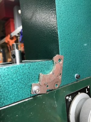
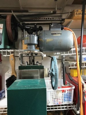
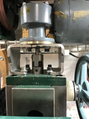
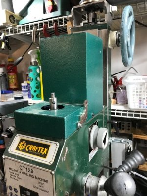
Took some time this morning while my beans are still full of dew to get the cover off, investigate options, and write this post. There are lots of options. That big bull gear literally screams "PICK ME, PICK ME!"

1. I could drill a hole in the side of the housing to install an automotive engine position sensor as I described in an earlier post on this thread above. The sensor will need a long tip to reach the bull gear through the housing but then all the wiring would be external and this option would sure make it easy to replace a bad sensor.

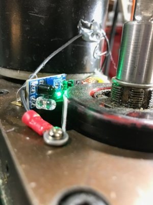
2. Or attach a small magnet to the top of the gear and a hall effect sensor in the cover above it. This introduces a possible balance issue. But I could always add a counter weight at 180 degrees. This will require internal wiring, but entire kits are available off the shelf for $30 - nothing to do but hook it up.

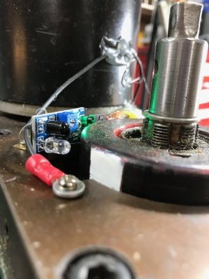
3. Or an optical sensor similar to what @whydontu described. But the entire bull gear area is packed with grease and I don't think grease and optical sensors will like each other very much. Also, there is no place for a shutter style window so it would have to be reflector style.

Or.....???

Prolly because of my automotive career I am leaning heavily toward using the engine sensor. Most of all, I like the reliability and the high resolution.

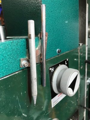
Anyway, it looks to me like it's nowhere near the ugly problem I originally thought it was going to be and installing a sensor shouldn't be that difficult after all. It's just a matter of making a good decision.

The electronics should not be too hard either. I do love the idea of using an Arduino, if for no other reason than the opportunity to learn how to use one! But I'm a bit worried about the speed limits because there are 81 teeth on the bull gear. At 4500 rpm (max Spd on the varispd dial), that's a counting frequency of 364,500 pulses per minute or 6,075 pulses per second (6KHz) which might be too fast for the arduino. Even if it is, that doesn't really matter. I'll use one if I can, and if not there are lots of single chip counters that can be used to generate an extremely accurate tach readout. I'd even bet I already have a few highspeed counter chips already in my electronics supplies.

THE FOLLOWING IS PURE SPECULATION BY A TOTAL IDIOT WHO NEVER USED AN ARDUINO BEFORE BUT WHO HAS USED MICROCONTROLLERS.

I confess that I am a little surprised that there are any concerns about the frequency limits of the Arduino Nano. It just doesn't seem reasonable that any microcontroller might not be able to follow a high frequency input. With a clock frequency of 16MHz, most microcontrollers can follow an 8MHz input, and 4MGz should be easy. So I did a little Arduino research this morning. Apparently, the Arduino IDE does not provide documented access to the full capabilities of the Atmega328P microcontroller itself. So I checked on the capabities of the microcontroller chip. As I had guessed it seems to have 5 hardware timers right on the chip that can be configured as an 8 or 16-bit TC with two compare/capture channels or one 32-bit TC with two compare/capture channels by using two TCS. It also has four 24-bit Timer/Counters for Control (TCC). All are rated at half the clock frequency (ie 8MHz).

So, unless I am all wet AGAIN, it ought to be possible to have the program setup and use a hardware counter (no additional code required except for setup) to count gear tooth pulses until it hits 81 (or any arbitrary higher or lower number, then increment an rpm counter or some such equivalence. A 20 pulse timer would prolly be accurate enough and would make it possible to calculate a high resolution rpm output that is refreshed at a decent rate (say once every 5 seconds). A hardware timer would eliminate the need for software to check the sensor state.

@whydontu - have you tried outputting an on/off pulse on one of the digital outputs from within your measurement loop to see how fast your program really is?

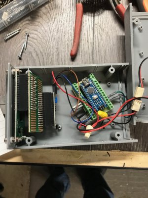
I also gather that the Nano board has to have some pin straps soldered to it before it can be inserted into the Nano Project Board but that the Nano Project Board makes wiring a lot easier after that. This seems really odd. Why wouldn't the Nano board come with the pins already on it? Or is that already an option I didn't see? Or maybe I just missed something....... I did notice that some of the photos had the pins and some didn't.

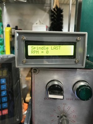
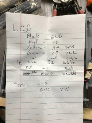
Is that display the brightest one available? Generally, I need reading glasses for such things so big bright digits are always a blessing. I saw some bright blue and bright green displays on the universal-solder website. But that could be just the photo or web image not the true size and brightness.

I plan to order a set of parts to play with once I get answers to the questions above.

Sorry for all the dumb questions.

And sorry in advance for prolly not replying AGAIN for a few days.......
 
Last edited:

Susquatch

Ultra Member
Administrator
Moderator
Premium Member
Here is my bull gear and below that is the proposed location of an engine position sensor. The socket I used for representation is 0.465" OD and that is probably still too big. A sensor with an OD of 3/8" would be ideal. Heaven forbid that I have to make one........

20211003_130347.jpg 20211003_130422.jpg
 

whydontu

I Tried, It Broke
Premium Member
Comments:

I‘m not familiar with the auto engine sensors, but my guess is it would work fine. My first attempt at the tach used a proximity switch, only problem was it was too big to fit inside my mill quill housing.

The update time on my software is pretty quick. Less than 1 second.

The smaller arduino cards can be ordered with soldered or not-soldered pin headers. I suppose you could use the not-soldered version and hard wire, but it makes it a pain to update any software. I use the pin headers and the terminal board so it’s easy to unplug the arduino and move it to my Mac when I want to modify the software.

LCDs have a contrast trimpot, my eyesight isn’t what is was 60 years ago but once I get the contrast pot set it’s easy to read.

The best I can recall was being able to toggle an output port at about 100kHz.

81 teeth @ 2000 RPM <should> be doable, but if I was doing this I’d put in a prescaler ahead of the arduino, a simple CMOS binary counter to divide the raw pulse count by 16 to reduce it to a range that’s going to work better with the arduino.

Higher speed tachometer:

https://www.instructables.com/Measure-RPM-DIY-Portable-Digital-Tachometer/

I didn’t use this design because I didn’t need the range, and the setup I used had only three active components, Nano, LCD, and IR sensor. This one needs a multiplexer and more parts than mine.
 

Susquatch

Ultra Member
Administrator
Moderator
Premium Member
Im not familiar with the auto engine sensors, but my guess is it would work fine. My first attempt at the tach used a proximity switch, only problem was it was too big to fit inside my mill quill housing.

The update time on my software is pretty quick. Less than 1 second.

The smaller arduino cards can be ordered with soldered or not-soldered pin headers. I suppose you could use the not-soldered version and hard wire, but it makes it a pain to update any software. I use the pin headers and the terminal board so it’s easy to unplug the arduino and move it to my Mac when I want to modify the software.

LCDs have a contrast trimpot, my eyesight isn’t what is was 60 years ago but once I get the contrast pot set it’s easy to read.

The best I can recall was being able to toggle an output port at about 100kHz.

81 teeth @ 2000 RPM <should> be doable, but if I was doing this I’d put in a prescaler ahead of the arduino, a simple CMOS binary counter to divide the raw pulse count by 16 to reduce it to a range that’s going to work better with the arduino.

Higher speed tachometer:

https://www.instructables.com/Measure-RPM-DIY-Portable-Digital-Tachometer/

I didn’t use this design because I didn’t need the range, and the setup I used had only three active components, Nano, LCD, and IR sensor. This one needs a multiplexer and more parts than mine.

You really are quite amazing you know.......

Since I believe that the Arduino microcontroller already has prescaling built in, I'd like to try and use that first. Especially since it can scale to any 8 or 16 bit variable desired. No need to revise circuitry, just change the program. However, the nature of the engine position sensor is such that the signal is probably way too low to be directly usable so I will need an amplifier anyway and I could add some signal conditioning to square up the sine wave and even add an external scaler if I need to.

Since I have no experience with the Arduino, I really don't know what I'm getting into by mixing machine code with the higher level Arduino code. Right now, I don't even know if that is possible, but I don't see why not. The original versions of C were loved by most programmers BECAUSE you could add machine language modules to the C code. We will see. If it doesn't work out, a prescaler is doable, but I'd like to try the direct approach first. I have already created an order at universal-solder. I will place it and let's see what happens. It will be a great winter project!

Since the head of my mill is already apart, I was going to drill for the sensor right now. But I have not yet decided which mill to keep so I think I will put it back together as is and do everything as a later project this winter instead. That will also give me time to read up on how to use the Arduino and play with it a bit. Heck, I could even chuck a gear in my lathe and test out the sensor and sensor circuitry before I make any permanent changes to the mill.

I have two followup questions before I order though. The picture below is the one for the Arduino that you specified above. As you can see in the photo, the pins are not attached so I had assumed that I would have to solder them on.
Screenshot_20211004-141442_Chrome.jpg

But your note above says "The smaller arduino cards can be ordered with soldered or not-soldered pin headers." I could not find it with them soldered on, but I would prefer that. How do I find that?

You also said that I could probably "use the not-soldered version and hard wire, but it makes it a pain to update any software. I use the pin headers and the terminal board so it’s easy to unplug the arduino and move it to my Mac when I want to modify the software." As I already said, that's my preference too. But I don't really understand what you mean by unplugging and moving to your Mac....... Unplugging it how? Do you mean unplugging it from the terminal board or unplugging everything from your mill?

Thanks again @whydontu!
 

whydontu

I Tried, It Broke
Premium Member
Soldered headers:

https://www.simcoe-diy.ca/product-p...-atmega328p-arduino-compatible-mini-usb-cable

I‘m cheap. To save $3 I’ll solder on the headers myself.

My builds always use the terminal boards, so I can remove the Arduino from the terminal board as needed:

> for when I fry an Arduino by shorting something, or accidentally putting a 12v signal somewhere it shouldn’t be

> for when I decide to change the software. Much easier to unplug the Arduino from the terminal board and move it to my Mac, leaving all the rest of the tach housing, sensor, and wiring still installed on my mill

Timing thoughts. There is a couple of lines in the code that define the ratio of sensor pulses in microseconds to RPM display:

duration = ( micros() - prevmillis ); // Time difference between revolution in microsecond
rpm = (60000000/duration); // rpm = (1/ time millis)*1000*1000*60;

probably all you’d have to do is tweak the 600000000 value to compensate for 81 pulses per revolution.

All of the data I can find online show a Hall effect automotive crank sensor as using 5 volt supply and signal. Wouldn’t need any tweaking to directly interface with the Arduino.

The original proximity sensor I used was a 12 volt output pulse, to use it with the 5 volt Arduino all I did was make up a simple resistor voltage divider.

My sensor only has one paint stripe on the target, so one pulse per revolution. For idle curiosity, I just added 9 pieces of reflective tape, so ten pulses per revolution. The tach read 11,000 at a true 1100 RPM, so it’s likely that the software could keep up with 81 pulses per revolution. The tape wasn’t evenly placed so the display bounced around a lot, but it was clear that the software was counting microseconds between pulses and converting to RPM.
 
Top