Got a GitHub?Next job is mitre/bevel gears with an involute cutter. Its all in the software!
-
Scam Alert. Members are reminded to NOT send money to buy anything. Don't buy things remote and have it shipped - go get it yourself, pay in person, and take your equipment with you. Scammers have burned people on this forum. Urgency, secrecy, excuses, selling for friend, newish members, FUD, are RED FLAGS. A video conference call is not adequate assurance. Face to face interactions are required. Please report suspicions to the forum admins. Stay Safe - anyone can get scammed.
-
Several Regions have held meetups already, but others are being planned or are evaluating the interest. The Calgary Area Meetup is set for Saturday July 12th at 10am. The signup thread is here! Arbutus has also explored interest in a Fraser Valley meetup but it seems members either missed his thread or had other plans. Let him know if you are interested in a meetup later in the year by posting here! Slowpoke is trying to pull together an Ottawa area meetup later this summer. No date has been selected yet, so let him know if you are interested here! We are not aware of any other meetups being planned this year. If you are interested in doing something in your area, let everyone know and make it happen! Meetups are a great way to make new machining friends and get hands on help in your area. Don’t be shy, sign up and come, or plan your own meetup!
You are using an out of date browser. It may not display this or other websites correctly.
You should upgrade or use an alternative browser.
You should upgrade or use an alternative browser.
Benchtop Hobbing Machine - The BHM
- Thread starter Arbutus
- Start date
-
- Tags
- cnc machines gears hobbing teensy
Dan Dubeau
Ultra Member
Impressive build.
Very nice.The BHM - a benchtop hobbing and gear cutting machine.
This project has been brewing for a couple of years and its now in a working, but not pretty stage, so I thought I would share a few details.
Gear hobbing is a highly efficient and accurate machining process used to create teeth on gears, splines, and sprockets. The multi-toothed cutting tool, called a hob, looks somewhat like a worm or a screw with cutting edges.
Here's how it works:
- The Setup:
- A gear blank (the workpiece that will become the gear) is securely mounted on a rotating spindle in a hobbing machine.
- The hob is mounted on a separate, synchronized spindle. The angle of the hob relative to the gear blank is precisely set based on the desired gear characteristics - specifically, the helix angle of the gear and the lead angle of the hob. When cutting spur gears, the gear helix is zero.
- The Synchronized Dance:
- Both the gear blank and the hob rotate in a precisely timed relationship. As they spin, the hob is slowly fed axially across the face of the gear blank.
- Think of it like the hob "rolling" with the gear blank as if they were already a meshed gear set.
- The Cutting Action:
- Each cutting tooth on the hob (called a "gash") takes a small chip out of the gear blank.
- Because the hob's teeth are arranged in a helical path and the hob itself is rotating and feeding, the successive cuts progressively generate the desired tooth profile on the gear blank. The shape of the hob's teeth directly determines the shape of the gear teeth being cut (typically an involute profile).
- Continuous Generation:
- The magic of hobbing is that it's a continuous generating process. The teeth are formed one after another in a continuous motion, rather than indexing and cutting one tooth space at a time (like in milling with an involute cutter). This makes hobbing fast and accurate for producing large quantities of gears.
- Because it is a generating process, exact tooth profiles for any number of teeth can be produced with just one hob. Involute cutters by comparison, are an average shape that is suitable for a specific range of teeth, e.g. a #4 cutter makes 21 to 25 tooth gears.
The BHM is designed to produce spur, helical and bevel gears - however we must use an involute cutter and an indexed action to produce bevel, miter and crown gears using the shift & rotate method.
The machine is built from barstock, with a 16" x 16 " footprint and 20" high. It weighs approximately 150 lbs.
There are the three linear axes, Z for depth of cut, Y for the work advance through the hob and X for transverse shift to utilize all of the hob length when it becomes worn.
When cutting helical gears, the gear helix angle is set manually with a quadrant plate.
When cutting bevel gears, the work axis can be tilted to match the various bevel angles.
The hob can cut either above or below the work, with the cutting forces directed towards the chuck.
The workhead spindle and the hob spindle are very precisely synchronised to generate the correct tooth profile. The hob spindle is driven by a large NEMA 23 servomotor, geared down 3:2 and the workhead is geared down 3:1 for increased torque. When cutting, the hob runs about 120 to 200 RPM and the gear blank at approximately spindle RPM divided by the number of teeth.
Originally I had intended to use a standard CNC control board to drive the steppers and servos. However AFAIK there is no precision spindle coordination that can be controlled using g-code, so I developed a custom controller based on the Teensy 4.1, and my own software and firmware to coordinate the 5 motors. The software is a continuous development (read 'neverending") process which is the cause of my grey hair.
The HMI (Human Machine Interface) is an 800x480 colour touch screen, and a custom 24 key keyboard.
Here's a few pictures of the machine at this stage and some finished gears. If there's a way to upload videos, I'll post those too.
View attachment 64649View attachment 64650View attachment 64651
Setting the gear helix angle on the quadrant plate, and setting the tilt to zero using a 123 block
View attachment 64647View attachment 64646
The undercarriage showing the X ballscrew and the hob helix adjustment mechanism.
The micrometer allows 1' (1 minute) adjustment.
View attachment 64645
Cutting a 60T M0.6 helical gear and a similar spur gear. Left/Right helical and a pair of spur gears made from Delrin.
Small gears like these take about 2 minutes to hob.
View attachment 64643View attachment 64642View attachment 64644
Custom electronics. Under the grey part are the 2M542 stepper drivers. There's a 24V 300W PSU plus a 5v and a 12v BEC.
View attachment 64641View attachment 64648
Stay tuned...
Amazing project worthy of a Gingery Style Book on the construction and programming.
Last edited:
So.....
Brass m0.6 gears are not a problem but cutting a steel (1045) m0.8 gear was a real shakedown test. Literally.
This is an m0.8 25 deg steel helical being cut just before I abandoned the job.

I had it set to a full depth of cut (1.8mm) with a very tiny feed of 0.25mm/work revolution. That doesn't sound like much but it sure made a lot of noise. About 3mm in and I could see that wasn't going to work. The Z (depth of cut) feed control is a work in progress - the goal is to set the DoC per pass so that the MRR (material removal rate) is reasonably constant. The plan is for the DoC to take a deeper bite on the first passes when just the cutting tip is engaged and reduce the DoC per pass as the shoulder of the tooth starts to cut. Probably overkill, but it will speed up the process and produce a smoother tooth profile.
The vertical column is fitted to a sleeve and base which can rotate +/- 4 degrees to set the hob helix angle. I was relying on the cotter clamp to keep the column in the correct hob helix position, but the offset cutting forces are too much for this, and there is some movement under high loads, so I will need to add another method of securing the column.
Much worse than that though, the spindle head should only move vertically - but again under high loads there is some rotational movement. So back to the drawing board for the column arrangement. I would like to cut a slot in the column - about 4mm deep and 12mm wide. On the inside of the head bore, I would fit a bronze key to mate smoothly with the slot. This should prevent rotation and allow only vertical movement.

Also, since the vibration shook out some of the setscrews that secured the column to its base, those will be replaced with pins and loctite.
More soon....
Brass m0.6 gears are not a problem but cutting a steel (1045) m0.8 gear was a real shakedown test. Literally.
This is an m0.8 25 deg steel helical being cut just before I abandoned the job.
I had it set to a full depth of cut (1.8mm) with a very tiny feed of 0.25mm/work revolution. That doesn't sound like much but it sure made a lot of noise. About 3mm in and I could see that wasn't going to work. The Z (depth of cut) feed control is a work in progress - the goal is to set the DoC per pass so that the MRR (material removal rate) is reasonably constant. The plan is for the DoC to take a deeper bite on the first passes when just the cutting tip is engaged and reduce the DoC per pass as the shoulder of the tooth starts to cut. Probably overkill, but it will speed up the process and produce a smoother tooth profile.
The vertical column is fitted to a sleeve and base which can rotate +/- 4 degrees to set the hob helix angle. I was relying on the cotter clamp to keep the column in the correct hob helix position, but the offset cutting forces are too much for this, and there is some movement under high loads, so I will need to add another method of securing the column.
Much worse than that though, the spindle head should only move vertically - but again under high loads there is some rotational movement. So back to the drawing board for the column arrangement. I would like to cut a slot in the column - about 4mm deep and 12mm wide. On the inside of the head bore, I would fit a bronze key to mate smoothly with the slot. This should prevent rotation and allow only vertical movement.
Also, since the vibration shook out some of the setscrews that secured the column to its base, those will be replaced with pins and loctite.
More soon....
And the root cause of the vibration under high load.....
These things.

I used these couplers on the X and Y axes. They are fine for light duty rotary transmission - but axially, they are springs!
Under the light loads when cutting plastic and brass, any axial movement was not noticed, but when cutting steel it got ugly. As the cutter does it's thing there are radial and axial forces which moved the workhead in the X and Y directions.
Stay tuned...
These things.
I used these couplers on the X and Y axes. They are fine for light duty rotary transmission - but axially, they are springs!
Under the light loads when cutting plastic and brass, any axial movement was not noticed, but when cutting steel it got ugly. As the cutter does it's thing there are radial and axial forces which moved the workhead in the X and Y directions.
Stay tuned...
Beautiful work.
Lotsa learning this week. Mixed in with a load of Fusion Confusion.
The F360 models are quite complex - 9 major subassemblies with around 350 parts and synchronized motion. Every once in a while, at random and for no possible cause and effect that I can find - an assembly will disintigrate. All the joints exist and are apparently valid, so the only recourse is to backtrack down the history timline. The trouble is - the issue can lie in an entirely different component or assembly. That was about 3 days of frustration and I still have no idea what's behind it.
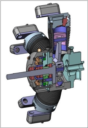
The full assembly nicely rendered in Fusion 360

Workhead with gear and the hob in the setup position

Some wireframe views


And with the entire machine stripped down, I cleaned up the base - a 12" length of C12-25 channel - and prepped it with a rustoleum primer, followed by a couple of coats of Ford tractor enamel.

Stay tuned... 🙂
The F360 models are quite complex - 9 major subassemblies with around 350 parts and synchronized motion. Every once in a while, at random and for no possible cause and effect that I can find - an assembly will disintigrate. All the joints exist and are apparently valid, so the only recourse is to backtrack down the history timline. The trouble is - the issue can lie in an entirely different component or assembly. That was about 3 days of frustration and I still have no idea what's behind it.
The full assembly nicely rendered in Fusion 360
Workhead with gear and the hob in the setup position
Some wireframe views
And with the entire machine stripped down, I cleaned up the base - a 12" length of C12-25 channel - and prepped it with a rustoleum primer, followed by a couple of coats of Ford tractor enamel.
Stay tuned... 🙂
Looks like F360 does not have the equivalent of SW 'lightweight' components? Poop. That functionality provides options to deal with big assemblies in different ways that better utilize memory & faster processing. Or in some cases just processing without failing. At a certain stage of 3D modelling, depending on part & assembly complexity + number & types of mate constraints + your PC memory/processing power, yes things can get unstable & unpredictable to the point of choking (in any CAD program). Behind the scenes, SW lightweight somehow compacts the sub-assembly into something more akin to a single part(ish) from a processing standpoint. So a 100-part subassembly with 300 mates becomes something more like a single part 'entity' within the primary assembly. End result us its not crunching through all those basically redundant surfaces & mates which may or may not have anything to do do with what you are trying to evaluate anyway.
The next inevitable issue that comes up is you require a mate within one (lightweight=pseudo locked) sub-assembly that must respond to a part/mate in another SA. In SW I can also selectively un-suppress those specific mates leaving the majority of others locked, so functional but still speedy. This doesn't do you any good in F360 if they don't support it, but just mentioning its a thing.
There may be other techniques - mock up only the critical motion components & selective suppressing unrelated components, sometimes fiddling with the history tree order. But that can have its own issues & is a lot of work. Before we go there, does F360 provide you any assembly model diagnostics tools that show where your resources are going?
I was going to do a motion animation of my radial engine. I had it working on a single cylinder basis. It correctly handles the planetary gear reduction right through cam/pushrod/rocker/valve train which has a pretty funky mate chain. Theoretically it should have carried this to the other 4 cylinders but it 'digitally seized' - a bad omen LOL. There other settings I need to figure out. Maybe radially copying the jugs (more efficient assembly memory) had some side effects. I've seen some radial/rotary YouTube videos where I can spot some motion cheats, others look to be good. But I digress...
Attachments
I was in the Musée des Arts et Métiers in Paris yesterday, and saw this gear hobbing machine designed and made by Theodore Olivier circa 1841.

It cuts inside or outside gears - the configuration is currently set for inside, where the blank runs through the annular cutter and is guided by the horizontally set guide wheels on the top arms. They adjust for the radius of the gear.
The outside hobbing head is below, and I have no idea how it mounts to the machine, though I'm certain the two arbors you can see behind it are also part of this setup.
Ingenious! I had not heard of Theodore Olivier so I dug a little deeper...
Théodore Olivier (1793-1853) was a prominent figure in the development of descriptive geometry and the theory of gearing. He was a professor at the École Centrale des Arts et Manufactures and also lectured at the Conservatoire National des Arts et Métiers, the parent institution of the museum. Olivier was known for creating intricate and illustrative three-dimensional models of geometric surfaces and gear systems.
But I couldn't find any on-line references for this machine which is a very interesting design. It would appear to be able to cut helical gears too, with the hobbing head pivoting relative to the work axis.
No it does not, unfortunately. The memory/complexity/Euler-math-fail is very probably the source of the problem in Fusion. Over the years I have found a few strategies to help - for example making certain that every component is completely self contained and fully referenced with a foundation reference which must not change for the life of the model.Looks like F360 does not have the equivalent of SW 'lightweight' components?
This helps with the lost joint issues but not with memory limits.
The Euler math problems (conflicting joints) are mitigated by using the foundation reference and by reducing complexity.
For example, I do not mate a collection of fasteners to the part with a joint for each. Instead, I position all fasteners, create a rigid group so they cannot move relative to each other, then I mate one fastener to the part. The part is mated to the foundation. That way only 2 joints are referenced instead of one per bolt. This really makes a difference when the fastener is an assembly eg. nut-washer-screw.
Complex kinematics often fail as well. Motion sync between components is achieved with "motion links" not with standard joints. I much prefer Solidworks or Inventor for that type of modelling.
I have a list of Fusion gripes longer than my arm. Despite being a beta tester, issues like this don't seem to get much traction from the complaints department.
Lots of updates and tuning after the shakedown test! Lesson #1 don't rely on set screws. Lesson #2 Turn on brain before operating machinery.
I rebuilt the column and key as mentioned before, which improved the column rotary lock significantly. The head is now rigid with respect to the base, but free in the Z direction.

The software now incorporates a smart DoC calculation to adjust the pass depth according to the material removal rate, which I figured could be modelled as a triangle (approximating a gear tooth profile) with each pass nipping a depth proportional to the (tooth area/number of passes). It works very nicely. The effect is for the tooth tip to bite deeper on the first pass, and on each following pass take a little less, until the final DoC is reached.
The second update was to add a touch-off probe so that the hob position touching the work can be set correctly (G54 equivalent). So that all works, the hob approaches, touches the probe, retracts 5.00mm and the work position is recorded. But my wobbly hands don't hold the probe in the correct attitude reliably. On these small gears, <M1.0, a thou or two makes a huge difference to the fit, so a more reliable method is needed and I'm looking for suggestions on how to make the touch-off process repeatable.
The probe is just a contact plate. I also have a touch button to signal the position when I visually jog into place, then I hit the button and the position is recorded. Parallax and old eyes aren't helping in that situation either.
One other issue is that the hob tooth must be at the lowest position.

Here's the issue:
When cutting a spur gear, the hob and the work axis are at 90 degrees +/- the hob helix (e.g. 1.13 deg). When touching off, the contact point between the two cylinders is easy to find. Furthermore, any axial misalignment of the hob or the work makes no difference, the Z position is always the same.

When cutting helical gears, that is not true. There is a point of contact which we must find, and any misalignment of the hob and work axes affects both the depth of cut and the tooth profile to be hobbed.
The X position is along the length of the hob but since the blank lies at the helix angle, there is only one position on the curved surface which is exactly at the top.
The axial feed during cutting is in the Y direction - the gear axis.
The Z position must be found at the centre of the work top surface - at the correct X and mid-Y positions. This becomes the work datum.


This is the result of a poorly aligned hob - the sides of the tooth have been shaved away by the hob, exaggerating the width, when the work and hob axes were offset slightly - maybe 5-10 thou in this example.

And the correct profile:

Stay tuned...
🙂
I rebuilt the column and key as mentioned before, which improved the column rotary lock significantly. The head is now rigid with respect to the base, but free in the Z direction.
The software now incorporates a smart DoC calculation to adjust the pass depth according to the material removal rate, which I figured could be modelled as a triangle (approximating a gear tooth profile) with each pass nipping a depth proportional to the (tooth area/number of passes). It works very nicely. The effect is for the tooth tip to bite deeper on the first pass, and on each following pass take a little less, until the final DoC is reached.
The second update was to add a touch-off probe so that the hob position touching the work can be set correctly (G54 equivalent). So that all works, the hob approaches, touches the probe, retracts 5.00mm and the work position is recorded. But my wobbly hands don't hold the probe in the correct attitude reliably. On these small gears, <M1.0, a thou or two makes a huge difference to the fit, so a more reliable method is needed and I'm looking for suggestions on how to make the touch-off process repeatable.
The probe is just a contact plate. I also have a touch button to signal the position when I visually jog into place, then I hit the button and the position is recorded. Parallax and old eyes aren't helping in that situation either.
One other issue is that the hob tooth must be at the lowest position.
Here's the issue:
When cutting a spur gear, the hob and the work axis are at 90 degrees +/- the hob helix (e.g. 1.13 deg). When touching off, the contact point between the two cylinders is easy to find. Furthermore, any axial misalignment of the hob or the work makes no difference, the Z position is always the same.
When cutting helical gears, that is not true. There is a point of contact which we must find, and any misalignment of the hob and work axes affects both the depth of cut and the tooth profile to be hobbed.
The X position is along the length of the hob but since the blank lies at the helix angle, there is only one position on the curved surface which is exactly at the top.
The axial feed during cutting is in the Y direction - the gear axis.
The Z position must be found at the centre of the work top surface - at the correct X and mid-Y positions. This becomes the work datum.
This is the result of a poorly aligned hob - the sides of the tooth have been shaved away by the hob, exaggerating the width, when the work and hob axes were offset slightly - maybe 5-10 thou in this example.
And the correct profile:
Stay tuned...
🙂
Pardon my ignorance and maybe its been tried, and the devil is in the details, but what if you could reliably know the relationship in Z between the center line of the hob and the gear blank, and using those, and the measured diameter of the hob and blank, end up with the correct tooth cut?
So that rather than relying on touch off, especially on the helical gears you could do it through math?
So that rather than relying on touch off, especially on the helical gears you could do it through math?
Lots of upgrades recently.
Thanks @Mike R for the probe suggestion. I reworked the software and the HMI to include an autoprobe function.
This is the electrical contact probe with a delrin insulating sleeve inside. The work arbor shaft size is also known, so the precise work axis to spindle axis position is known. It is a very repeatable and reliable system.


It really helps when making smaller gears like this m0.5 brass pinion.

Most of the work this month has been fighting the HMI. The display I have been using is a Nextion "Intelligent" 800x480 capacitive touch screen. It is quite easy to use with the Teensy for most operations. The HMI has seven screens - the main Console, Jogging with DROs, Job setup, Machine setup, Material setup, Hob setup and Help. When changing screens, the application needs to remember what was displayed, change screens, display data and then when returning to the first screen, refresh the screen with the saved data. With the Nextion system the time needed to refresh the display is approximately 1 second which is completely unacceptable, since the machine may have changed state in that interval.
The issue was ultimately traced to how the Nextion handles Serial data, basically creating a parsing bottleneck on the display which I cannot work around easily. 4D Systems also make intelligent displays and I have had some good experiences with those in the past, So I pulled the trigger on a 5" 800x480 uLCD display programmed with VisiGenie.
The VisiGenie software is entirely different in concept and operation than the Nextion. The BHM application is independent of the HMI, so I began a complete refactoring which seems to be working so far.
Here's the Jog screen and the Job setup screen:
The SYNC button sets the relative rotational position of the work and the hob (index = 0) so that a repeatable starting position can be set.
PROBE starts the autoprobe sequence
TOOLS_OK signals that the hob and workpiece are loaded, after the PROBE cycle.
POS_OK is set when the hob and the blank are at the touch-off position.

Almost all of the calculations are performed in the background after the user parameters are entered. When the number of Gearteeth, Hob, Helix and Width are set, the gear can be fully defined. The blank diameter and Y travel are calculated. When the material is selected, the system will make an educated guess for the number of cutting passes and the optimal depth of cut per pass. These can be overridden by the user.

Stay tuned....
Thanks @Mike R for the probe suggestion. I reworked the software and the HMI to include an autoprobe function.
This is the electrical contact probe with a delrin insulating sleeve inside. The work arbor shaft size is also known, so the precise work axis to spindle axis position is known. It is a very repeatable and reliable system.
It really helps when making smaller gears like this m0.5 brass pinion.
Most of the work this month has been fighting the HMI. The display I have been using is a Nextion "Intelligent" 800x480 capacitive touch screen. It is quite easy to use with the Teensy for most operations. The HMI has seven screens - the main Console, Jogging with DROs, Job setup, Machine setup, Material setup, Hob setup and Help. When changing screens, the application needs to remember what was displayed, change screens, display data and then when returning to the first screen, refresh the screen with the saved data. With the Nextion system the time needed to refresh the display is approximately 1 second which is completely unacceptable, since the machine may have changed state in that interval.
The issue was ultimately traced to how the Nextion handles Serial data, basically creating a parsing bottleneck on the display which I cannot work around easily. 4D Systems also make intelligent displays and I have had some good experiences with those in the past, So I pulled the trigger on a 5" 800x480 uLCD display programmed with VisiGenie.
The VisiGenie software is entirely different in concept and operation than the Nextion. The BHM application is independent of the HMI, so I began a complete refactoring which seems to be working so far.
Here's the Jog screen and the Job setup screen:
The SYNC button sets the relative rotational position of the work and the hob (index = 0) so that a repeatable starting position can be set.
PROBE starts the autoprobe sequence
TOOLS_OK signals that the hob and workpiece are loaded, after the PROBE cycle.
POS_OK is set when the hob and the blank are at the touch-off position.
Almost all of the calculations are performed in the background after the user parameters are entered. When the number of Gearteeth, Hob, Helix and Width are set, the gear can be fully defined. The blank diameter and Y travel are calculated. When the material is selected, the system will make an educated guess for the number of cutting passes and the optimal depth of cut per pass. These can be overridden by the user.
Stay tuned....
Last edited:
Very cool!
Yep, but not public yet. I'll probably publish the s/w when its stable.Got a GitHub?