• Scam Alert. Members are reminded to NOT send money to buy anything. Don't buy things remote and have it shipped - go get it yourself, pay in person, and take your equipment with you. Scammers have burned people on this forum. Urgency, secrecy, excuses, selling for friend, newish members, FUD, are RED FLAGS. A video conference call is not adequate assurance. Face to face interactions are required. Please report suspicions to the forum admins. Stay Safe - anyone can get scammed.

Ball ended taper turning

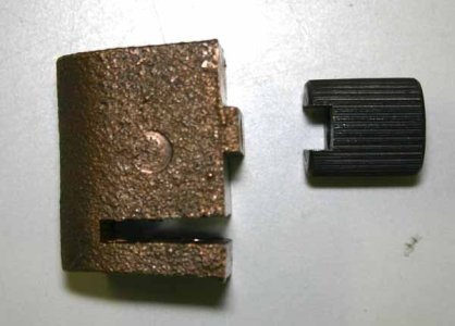
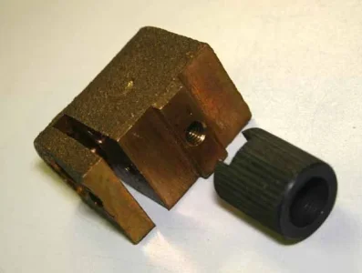
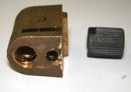
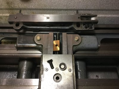
Here are the parts I was mentioning in post #6. (I ordered them as spares, I didn't remove them). Its a bit clearer to me now, but still not 100%. The steel plug has spline serrations so guessing is a press fit into the table hole. It has a groove that engages a matching raised boss on the top of the bronze lead screw nut & held captive with a cap screw. The fit is particularly tight although that might just may be typical rough tolerance? I say that because when I loosen the bolt on my lathe now, the nut becomes free (or did I push it down a bit to disengage... now I cant recall).

Anyway thinking out loud here - if the plug were somehow removable or even 'raise-able' so the table would slide over the nut without interference, that would allow the table to be guided with a taper bar assembly. After that, reposition the table hole over the nut & re-engage bolt to lock it down again. There must be something I'm missing, it couldn't be that easy. Otherwise why the telescoping lead screw stuff?
John, try the mod on your lathe first :)
 

Attachments

  • 001_edited-1.jpg
    001_edited-1.jpg
    23.6 KB · Views: 10
  • 002_edited-1.webp
    002_edited-1.webp
    19.1 KB · Views: 10
  • 003_edited-1.webp
    003_edited-1.webp
    18.5 KB · Views: 10
Anyway thinking out loud here - if the plug were somehow removable or even 'raise-able' so the table would slide over the nut without interference, that would allow the table to be guided with a taper bar assembly. After that, reposition the table hole over the nut & re-engage bolt to lock it down again. There must be something I'm missing, it couldn't be that easy. Otherwise why the telescoping lead screw stuff?
John, try the mod on your lathe first :)

No, I don’t think you are missing anything: that’s how simple it is on my 9” Utilathe and is how SM do it on that small lathe.

The reason for the telescopic set-up is (as far as I can tell) so you retain the in-feed capability of the cross slide. So, for example, you can still single point thread using the compound @ 60* and only cut on one edge of your threading tool. With the cross slide nut “floating”, in-feed is only possible with the compound and, when threading, you’d be cutting on both edges of the threading tool (not that that is necessarily bad, just takes a better tool, more power, and will possibly result in more chatter).

The serrated plug on your lathe serves the purpose of giving the manufacturer the chance to adjust the lead screw plane parallel to the cross slide plane. I had a lathe where the compound would bind up the more I retracted it away from the work. I thought the lead screw was pooched. Turns out the nut was mounted too far below the underside of the compound and would bend the lead screw. Not too much of a problem when the nut was at the extreme end of the screw; but as it got pulled in to where the lead screw was supported in its bearing (at the dial end) the bending force got too large and it would bind. Milled some metal off the nut to make the two planes run parallel and no more issue.

In your case, they probably just set the serrated plug deeper/less deep into the cross slide to make the lead screw run parallel to the cross slide. The mortise and tenon arrangement of your plug/nut is (I assume) to take the “slop” out of a simple bolt/threaded hole connection. It also reduces wear by being a close tolerance fit. The bolt just holds the joint together and is not under any shear forces that could wear out the threaded hole. There may also not be enough meat in the soft nut for a good size bolt - hence the mortise and tenon arrangement. Quite clever.
 
Last edited:
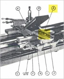
Rudy, thanks for your patient explanation. I overlooked some details of your user manual page. Now I see where they talk about releasing the nut which is the equivalent of what I was wondering about. Looks like a nice feature on that lathe is a flip-up cover so allow easy access. Mine would be all blind under the table. Also, very good point about the threading operation, another factor to consider.

I never even considered the serrations were for lead screw plane height adjustment, another good point. I was thinking if that table hole was threaded, one could screw the insert out to disengage the lead screw nut. But then you need a way to re-establish the datum again + some other fiddly complications. 'Next' lathe will have a taper attachment for sure!
 

Attachments

  • 2017-11-19_11-04-08.webp
    2017-11-19_11-04-08.webp
    12.5 KB · Views: 7
You are welcome Peter. It makes me think how things work and why the engineers may have designed it the way they did when folks ask questions. I don’t mind at all.

Here is a sequence of pictures showing the taper set-up on the SM 9” Utilathe (the instructions and the one image out of the owner’s manual have been posted above).

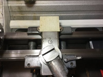
The nice original cover for the cross slide extension got lost somewhere along its 52 year history. So I made my own and just remove the extension when I don’t use the taper attachment. I also remove the taper slider block and slide and cover the bare mounting structure, as seen here
C5F24486-452D-4AC0-954B-4040D37A352F.jpeg

You can clearly see the CS lead screw retaining bolt & washer, just above the compound.

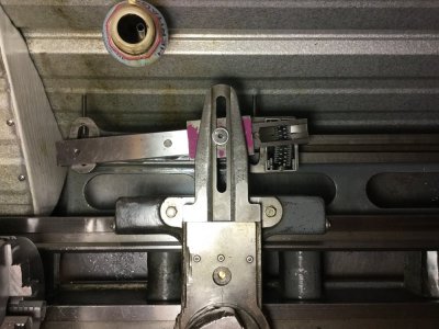
The next picture shows all covers removed, the bolt & washer removed, the CS nut further along the lead screw and the taper attachment slide installed on its support.
2BCC2974-2CB7-48C8-91FC-3264393731AB.jpeg

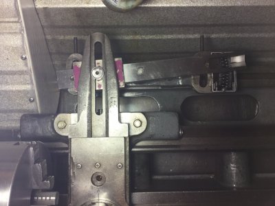
Here we have the CS extension attached to both the CS and the slider block of the TA (this uses the same bolt & washer that holds the CS nut in place). If you look carefully, you can just make out the brass nut in the hole of the CS. The lead screw is not controlling the lateral motion any more. The saddle longitudinal motion, together with the TA slider move the CS laterally; the amount being dependent on the angle set on the TA.
42848553-E9A7-4BEA-9A4E-60CDFE65F226.jpeg

Here is the carriage a little further along the TA.
BE0E476C-5E76-4FA2-AF24-960DA839EE8B.jpeg

The useful range is about 8” of taper turning. Has been long enough for my needs.

Ball center turning would only be limited by the distance between your centers and the off set angle. As stated before, I would give it a try if I needed to turn a taper that’s longer than my compound travel and I did not have a TA....
 
Last edited:
Update: I followed RobinHood's tutorial to the letter and had a good weekend at home with the lathe. I sacrificed one of the Grizzly MT 4.5 adapters (has MT3 inside taper) and attempted to machine as described.

The first challenge of course was to properly set the cross-slide to the correct angle, and after some trial/error I was able use the long-needle DTI to register near 0 as I move in/out of the spindle taper.

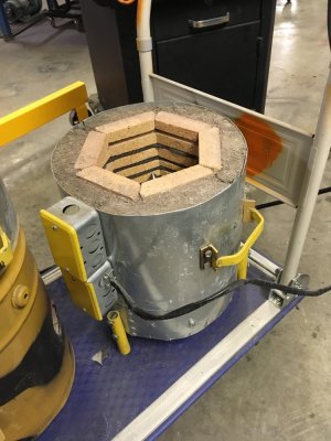
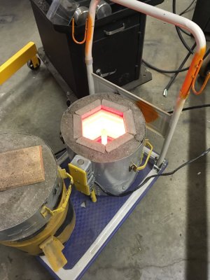
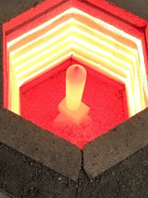
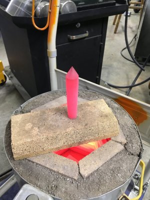
The second challenge was turning the adapter, which was hardened. Top speed on this old girl is about 600 rpm, and the test pass wasn't pretty so I took stock of the situation and decided to try annealing it. I put my electric kiln to use and heated it for 1 hour 15 minutes (typically enough time to melt 5 pounds aluminum from dead-cold). The adapter was a nice orange-red and I removed it and let it cool for 8 hours on a brick above the kiln (slow cool). After remounting, this sure machined nice with any bit I had.

After making the cuts, and then undercutting it (thx for the tip), I removed the chuck and mounted. Moment of truth................ not concentric. It reads out (depending on the adapter rotation) anywhere from 0.002 to 0.010. not desirable I think -- I wonder what impact that would have on the end result of turning between centers...... something to test.

I re-did my procedure (setting the angle) and took another pass at the adapter, remounted.................same results. I indicated the spindle and there is definitely 110 years of love/abuse that have occurred. It is neither shiny nor smooth (nor round it would seem.).

The positive here though is that this was the best case attempt -- a way to get an adapter without having to bore the ID taper. The real positive here is that the adapter fits REALLY well in the spindle (as evidenced by blueing) so I believe the work I did on setting the angle is valid.

Lots of firsts this weekend...... first time using a lathe dog (stand to the left, hold breath and hope it stays put), first time annealing, improved results on HSS sharpening etc.

Next step, machine a plug , step-drill and MT reamer.
 
Glad to hear you made some progress and learned something along the way. I call that a good day.

Your last paragraph: machine plug, step-drill and MT reamer sounds like a good idea. How are you planning on making sure that, once the plug is machined, you will be able to insert it in exact same location (radially in the spindle) when you use it next time? I could foresee run out if it does not end up in the same position and all your hard work was for nothing.

From your comments above, it seems to me that the spindle bore may have some run out itself or the spindle is bent or has slop in the bearings. Have you checked on that? There is a good video by Wes Johnson, “Worn Engine Lathe Evaluation”, specifically @ 5:26 he shows how to check for spindle play - might be worth investigating.

Hopefully all the above is in order and you do not have any of those issues.

After making the cuts, and then undercutting it (thx for the tip), I removed the chuck and mounted. Moment of truth................ not concentric. It reads out (depending on the adapter rotation) anywhere from 0.002 to 0.010. not desirable I think -- I wonder what impact that would have on the end result of turning between centers...... something to test.

Here is how I would overcome this issue: centers do not have to be hardened to be useful. Since you can successfully anneal, I would do that to a designated MT center that you already have and insert it into your plug that you just worked on and seat it well. Then just turn the point on it before you use it (I believe I suggested that previously with a center held in the chuck). That would also save you making a whole new adapter and buying an expensive MT reamer. Plus it would not matter how you insert the plug into the spindle as you will always be concentric after you turn the point. Drawback: it takes a little extra time and your center will get shorter each time you take a skim cut off it.

If you don’t mind me asking: where did you get your kiln? Make and model # perhaps? That is one area I am not set up well: heat treating.
 
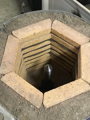
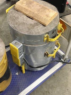
I made my kiln for the purpose of melting aluminum/brass for casting

I followed a book (one of gingery) and ordered the element from budgetcastingsupply.com

I built the bases (top/bottom) as separate pieces and I have a propane fired middle section that u swap out in summer (Electric=indoors)

The kiln is made of firebrick (w/grooves cut on table saw) that hold the element, surrounded by refractory


Sent from my iPhone using Tapatalk
 
1 hour, 15 minutes. The last picture is the center in the 'cooling' mode. The heat from the kiln will keep it warm for hours. Furnace will be glow for an hour after unplugging.
 
Yep, the plug is in a 220v 15 amp breaker, based on the length of heater wire, it draws juuuussst over 15 but it won't trip the breaker


Sent from my iPhone using Tapatalk
 
It runs off a stove (think household stove) switch .those work on a principle of on/off cycles. Max= always on. I rarely use it on a setting other than max , but I'm going to use it for some lost pla plaster of Paris castings to melt the pla out of some molds


Sent from my iPhone using Tapatalk
 
Kevin, that is a superb kiln you have there. Good job on building it.

Just the thing I am looking for. I am going to get more details of the build from you, if you don’t mind, when I’m ready to make one.

Thanks for sharing.

Cheers, Rudy
 
Back in post #21 I was showing the serrated steel insert that goes through the cross slide & engages the top of lead screw nut.
I found this interesting post. Its a bit long & mostly deals with a new nut. But he also discusses this insert component. As with most parts on these machines, there is more than meets the eye, particularly involving extraction & setting. My personal conclusion: don't tinker with this to make a homebrew taper attachment unless you are prepared to go for gold! :)
http://www.metalworkingfun.com/showthread.php?tid=2088
 
@PeterT : I totally agree with you regarding the fact that if you want to upgrade your lathe with a shop made TA, one must be willing to “improvise” and solve problems as they arise. I just skimmed over the posts in the link you provided: sure looks like the fellow had a few obstacles to overcome on the way of his success.

Pierre from Pierre’s Garage just recently posted a video of the telescopic TA on his lathe; the one on my SM 1340 is very similar. Might give you a little more info as to what may be required to retrofit your machine with one...
 
Back
Top