• Spring 2024 meetup in Calgary - date Saturday, April 20/2024. discussion Please RSVP Here to confirm and get your invitation and the location details. RSVP NOW so organizers can plan to get sufficient food etc. It's Tomorrow Saturday! you can still RSVP until I stop checking my phone tomorrow More info and agenda
  • We are having email/registration problems again. Diagnosis is underway. New users sorry if you are having trouble getting registered. We are exploring different options to get registered. Contact the forum via another member or on facebook if you're stuck. Update -> we think it is fixed. Let us know if not.
  • Spring meet up in Ontario, April 6/2024. NEW LOCATION See Post #31 Discussion AND THE NEW LOCATION

Ball ended taper turning

PeterT

Ultra Member
Premium Member
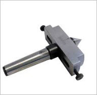
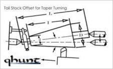
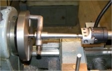
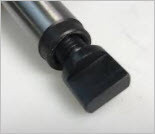
At the last meet-up at Modern Tool I was talking to someone (my apologies, forgot name) about cutting tapers using stock supported by ball ends when you don't have a taper attachment. I first saw this method in a model engineering magazine on a Myford lathe & the guy made all sorts of tapered shank tooling. The idea is you can leave your tailstock in its zero axial position & insert a device into tailstock that does the requisite offset similar to attached pic. Also you don't have to buy special center drills with curved profile meant to facilitate problem of 60-deg dead center running offset in 60-deg countersink.

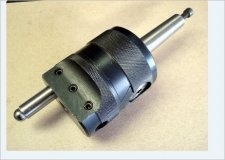
I found some pics using a boring head which to my simple mind seems a lot easier than a separate, dedicated attachment. I'll admit some of those setups make me a bit squeamish, especially the high angle one. But maybe (hopefully) using shallow cuts....

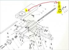
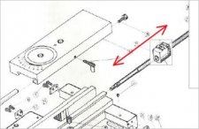
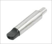
Anyway, I got thinking about how to A) orient the tailstock device so its in center plane and B) but then also prevent rotation in tailstock barrel? Most of the MT3 boring head arbors don't have a tang like a drill arbor. I think if they are intended for a mill they have threaded end for drawbar? I see the occasional one like this. I guess the trick is find one that has correct threads for boring head & yet extended/tang on taper end.
http://pacifictoolandgauge.com/ream...taper-3-mt3-boring-head-arbor-7-8-20-tpi.html

But getting back to A), once you screw in the boring head to the arbor, you have no control how the head center will line up to the tang. On a drill we don't care, it just resists motion. But here we need the dovetail to act horizontally. I cant figure out how guys do this?

Anyone mess around with setups like this?
 

Attachments

  • SNAG-11-12-2017 0006.jpg
    SNAG-11-12-2017 0006.jpg
    6 KB · Views: 13
  • SNAG-11-12-2017 0005.jpg
    SNAG-11-12-2017 0005.jpg
    45.1 KB · Views: 13
  • SNAG-11-12-2017 0007.jpg
    SNAG-11-12-2017 0007.jpg
    16.5 KB · Views: 13
  • SNAG-11-12-2017 0004.jpg
    SNAG-11-12-2017 0004.jpg
    62 KB · Views: 14
  • SNAG-11-12-2017 0003.jpg
    SNAG-11-12-2017 0003.jpg
    60.5 KB · Views: 13

John Conroy

member
Premium Member
Those set ups look pretty flimsy to me. Driving the stock with a dog does not provide much grip and you would have to take very light cuts. If there is any play in the tailstock shaft key there would be no way to prevent the shaft from turning back and forth the amount of the play. I've heard of this being done but it seems pretty dangerous to me. My mind keeps creating pictures of all those parts flying off at speed.
 

John Conroy

member
Premium Member
I know we talked about building a taper attachment a while back Peter and it's still rattling around in my head. There have been huge price drops in linear bearings and rails in the last few years and I've been looking at something like this to use as the main sliding component for a taper attachment.

25 mm linear bearing and rail.jpg

It is a 25mm linear bearing on a 21.5" long rail. That should be plenty strong enough and long enough for the job. $130 on Amazon
 

PeterT

Ultra Member
Premium Member
I know... why do I torture myself with taper cutting? (Mostly because I'd like to make some parts outside the range of compound travel). On our style lathe, when you buy it with 'taper attachment', what that really means is 2 things: the slider block assembly that mounts to the rear of lathe similar to what you show. And also a different lead screw assembly that has to disengage from the nut in taper cutting mode. Its a screw within a sleeve type deal. That wasn't apparent to me at the time when I had the choice to buy that way & more of a bugger to replicate. Your slider pic would work to set the angle if that's what you mean.

A semi-baked idea: On our non-taper cutting lathe style there is this post that engages the lead screw nut to underside of cross slide table. If you unscrew the bolt (and ???) could that allow the table to slide freely?. Now with taper bar attachment locked on, table moves under its control. In feed would be limited to using the compound lead screw. I'm still not clear if this would work. Something tells me when I was in there that unscrewing the bolt doesn't drop the nut out of position 9which is why you still have to unscrew lead screw until its off?). So it would require modifications & that's where I run out of enthusiasm.
 

Attachments

  • SNAG-11-12-2017 0011.jpg
    SNAG-11-12-2017 0011.jpg
    78 KB · Views: 12

PeterT

Ultra Member
Premium Member
I think my writing is confusing even to me! Maybe sketch will help. If the bolt & post were somehow removed & out of the picture, the nut would still be attached to lead screw. But now, hopefully the table could pass over it freely. The lead screw is now disengaged. So with any of the taper bar assembly mechanisms hooked up, table it would slide according to the bar angle. But its that post/bolt/bushing detail I'm still not clear on. I should have looked harder at the underside when I had it off.
 

Attachments

  • SNAG-11-12-2017 0012.jpg
    SNAG-11-12-2017 0012.jpg
    33.1 KB · Views: 4

John Conroy

member
Premium Member
In the box of parts you ordered for me there should be a cross slide lead screw nut. Maybe you can tell by looking at it. I have had mine apart but I don't remember if there is anything on it that would prevent it from sliding freely when the bolt and spacer are removed. I'll check that out later by removing the bolt and spacer and trying to slide the cross slide along the ways.
 

Dabbler

ersatz engineer
regarding the boring head attachment, my friend Bert does some very accurate work by offsetting the work in a dead center held in a boring bar attachment. That being said, he only does very small offsets, never more than .250 off center in any direction. The boring head could be used for very shallow or short tapers, but not the one you pictured.

I agree the MT3 arbor with a slider looks very flimsy for all but the softest materials and shallowest cuts.
 

RobinHood

Ultra Member
Premium Member
A semi-baked idea: On our non-taper cutting lathe style there is this post that engages the lead screw nut to underside of cross slide table. If you unscrew the bolt (and ???) could that allow the table to slide freely?. Now with taper bar attachment locked on, table moves under its control. In feed would be limited to using the compound lead screw. I'm still not clear if this would work. Something tells me when I was in there that unscrewing the bolt doesn't drop the nut out of position 9which is why you still have to unscrew lead screw until its off?). So it would require modifications & that's where I run out of enthusiasm.

Peter, you are correct, if the cross slide lead screw nut does not fully release and allow free sliding, modifications to the way the nut is mounted to the cross slide will be required.

Here are the instructions from my SM 9” Utilathe with taper attachement. Removing bolt A completely releases the cross-feed nut. Cross slide movement is now slaved to the taper bar angle. Infeed, as you correctly suggest, is through the compound.

66FC9EFF-2B15-4B0F-8241-E6E608488CE1.png

Here is a comparison of the SM1340 without taper attachment and with telescopic taper attachment. Note the way more complicated lead screw end support for the lathe with a telescopic TA.... This is done so that set-up time for taper turning is reduced and the cross slide still controls infeed on the 1340.

Without TA
982F0967-A7C4-413A-B1C9-1C71D6B6CD27.png

With TA
05E3A66C-2CE3-44E6-B2C5-2FB1F9B12759.png

Let me know if I have completely confused you about taper attachments....
 

RobinHood

Ultra Member
Premium Member
Most of the MT3 boring head arbors don't have a tang like a drill arbor. I think if they are intended for a mill they have threaded end for drawbar?

I had the same issue with an ER32 collet holder, that has a MT3 shank, I wanted to use in my tailstock. Here is what I did to solve the problem...

1F2C78CF-5F26-463B-B063-B3FABAE56E93.jpeg

It is a 7/16-20 bolt modified (actally just turned) to take the place of the tang. I screw it into the back. Works great.
 

PeterT

Ultra Member
Premium Member
Re the screw-in tang adapter (nice job btw), I considered that but dismissed it thinking if the arbor sees torque it would just unscrew the end adapter? In a mill, the drawbar is pulling the arbor taper into the socket & locked down tight, but in a tailstock its just the initial seating action, no drawbar from the handle side. I figured you could make the screw-in tang permanent with a cross pin or something in order to use the arbor for tailstock, but no going back to mill? I found this pic which looks to be what you are doing (removable?). What am I missing here?
 

Attachments

  • SNAG-11-13-2017 0001.jpg
    SNAG-11-13-2017 0001.jpg
    3.7 KB · Views: 4
  • SNAG-11-13-2017 0000.jpg
    SNAG-11-13-2017 0000.jpg
    4.3 KB · Views: 4

RobinHood

Ultra Member
Premium Member
I agree that the arbor will see torque. If the taper fits properly, and is small enough (2-3* included angle) then there should not be enough torque to spin it in the socket. The Machinery’s Handbook refers to Morse Tapers as “self-holding .... because, ...., the shank of a tool is so firmly seated in its socket that there is considerable frictional resistance to any force tending to turn or rotate the tool relative to the socket” MH, 29th ed, pg 948.

I don’t think you are missing anything. Perhaps your tapers are just a little loose in thier tolerances and don’t hold very well?

Just the other day I had to remove a tool from a Morse Taper Socket extension and had one hell of a time get it out. It did have a tang, but that was not engaged on the side wall. So the tool did not rotate in the taper during use. It was held in place purely by the taper. Same thing happened to my brother at work: they ended up destroying two keys. They got it out with heat and a new key in the end.

Milling machines have different tapers in their spindles in that they have what the Machinery’s Handbook calls “self-releasing type” tapers (I do understand that some smaller ones have MT spindles - which would be a self-holding type). The popular R8 spindle is an example of a self-releasing type spindle/collet. It requires a drawbar to keep the tool securely seated in the socket. It is the friction of the taper that drives the tool and not the little locating pin. ER spindles/collets don’t even have any locating device and yet don’t spin when properly seated.

In your application of using a boring head with a dead center in it to dial in a certain amount of “off-center” for your taper turning on the lathe, I would not worry about the boring head spinning, if seated properly.

As others have pointed out, there could be some issues with the work staying put with heavier cuts / larger off-center distances. On the other hand, it is not much different than off-setting your tailstock by the required amount to turn the taper between centers; that technique is described in many old machining books.

The advantage of using a boring head for the off-set is that you don’t mess with the alignment of your tailstock.

Sorry, got a little long here....
 

PeterT

Ultra Member
Premium Member
Gotcha. I guess I'm still not 100% clear on what is actually inside my tailstock when it comes to 'tang retention'. I'm visualizing some sort rectangular socket or 2 flats that the extended tang portion would be positioned within. Yes the MT fit is doing majority of grip. I visualized the tang is as limiting free spin runaway if the tool ever jammed up? But looking at my parts sketch, I don't see anything that engages the arbor tang flats. I just see the feed/ejector rod. Maybe the tang feature its inside the barrel itself?

Back to the ball centered taper turning, what scares me is how the balls are attached to the end centers. One guy turned it from solid (PITA). One guy somehow brazed it. One locktited bearing balls into a c/sink recess. I can envision friction heat on the balls & maybe a bond letting go & bad things happening. Maybe turning on conventional centers & using the special curved center drills is net safer.
 

Attachments

  • SNAG-11-13-2017 0006.jpg
    SNAG-11-13-2017 0006.jpg
    91.7 KB · Views: 6

RobinHood

Ultra Member
Premium Member
Hi Peter,

Thanks for asking all those questions - it got me to really look at my machines to see what I have....

Here is a technical drawing for my SM 1340 showing the tailstock. If you look closely, you can see that there are two options for the spindle (besides inch and metric): one with tang drive, the other without. See section A-A (top corner) for a view of what it looks like.

E248516A-25BC-492B-A28C-9D9528E78910.png

Here is a picture (sorry for the poor quality) of what a tang drive spindle looks like in real life
EB0EBCE0-0862-4004-A00F-3F54DA4E4584.jpeg

And here is one from a standard spindle (non - tang drive)
F9875D21-2EEF-43D1-9D5C-6D8135D57869.jpeg

Turns out that my 1340 has tang drive and both the 1120 and 9” do not.

As far as the people using ball ended turning between centers: as long as the balls are deep enough into their sockets (ie they engage on their lagest part of their OD in the work piece) and the tailstock does not move axially, there should be no reason why this is any less secure than turning between conventional centers. I can see the limiting factor being the neck diameter at the root of the balls. And the material that these ball centers are made of.

I am no expert, of course, but I would give it a try if I did not have a taper attachment.
 

kevin.decelles

Jack of all trades -- Master of none
Premium Member
Gents, great discussion! I was part of the discussion at modern tool re: tapers. It started with a description of a quest I'm on the turn between venters

My lathe is vintage iron (Von wyck 16"'circa 1908). The issue I have is my spindle inside taper is unknown. Tailstock is mt3

Mt5 is too big, mt3 too small, I ordered dead centres for jarno 12 which fits but had a slight "rocking" (doesn't seat 100% centric).. I then found out about the Elusive my 4.5 (which is in some machinerys handbook editions but not all). I was able to get one of these from grizzly (special order) and it too is close but not perfect

That brought me to buying a very nice interapid dti with the 2.5" arm so I could indicate the spindle. This is a good exercise for a newbie as you need to be dead on centre and parallel to get a valid measurement

After repeating my measure about a dozen times, I figure the taper is a b&s #11. I ordered An adapter off eBay which was supposed to be b&s11 outer and mt2 inner. It arrives and it isn't b&s11 outer (not even close)

So after about trying, buying, testing, I am without a centre for my spindle, but would love to have a b&s #11 adapter

My next quest is to turn my own, which led to the taper discussion......

Any of you up to the challenge? I'll get there, im learning at a rapid pace, but this has been oh so painful


Sent from my iPhone using Tapatalk
 

PeterT

Ultra Member
Premium Member
Hi Kevin, thanks for the name reminder. I remember we were talking about this.

Boy that's a tricky one. I can appreciate what you are going through as I was trying to match an arbor taper, basically driving myself nuts making test plugs, trial fits with blue, re-adjust, re-tweak. Some textbook tapers came close but nothing bang on so I chalked it up to my setup / machining. Then one day I got the bright idea to call the manufacturer (who would have surely known I was trying to make my own arbor rather than buying their insanely spendy ones that wouldn't work for my purposes anyway). He said 'oh that's our own taper, X inches/foot; we do that so people don't plug in any old arbor'. Dang, well that explains it. In all fairness the arbors were for a high speed grinder so maybe they don't want people to shoot their eye out. Anyway, here I was tearing my hair out. I mention this just in case. If you had some literature that supported a specific taper standard, that would be the best starting point.

OD Taper
I know you have been through this, but maybe worth mentioning - when you line up a bunch of commercial 'common' tapers like this partial table & eyeball down the taper-per-inch, its amazing how close some get to one another from completely different families. I never realized this until I got into the guessing game myself of what taper do I even have? And a measly 1-thou difference over an inch stands out like a sore thumb fit wise. It will rock or snug up only a relatively narrow band as evidenced by blueing.
https://littlemachineshop.com/reference/tapers.php
Getting back to my first blah-blah, even if you were 100% certain of taper used, you may have oval-ing in your existing spindle due to wear or distortion. That will throw out the measurements because you might be tempted to take an average & that might explain the close but no cigar fit. There is no solution to this other than taking the 2 minimums because you are fitting a circle into an elipse.

ID Taper
The fact that your part adapter sleeve needs both inside & outside tapers makes this even more 'fun'. :) It seems to me the MT2 would be the more straightforward but still not a 5-min job
- finding a straight blank with MT2 pre ground & finished. Turn your OD taper from that stock. Not sure I have seen this, but doesn't mean it doesn't exist.
- boring the taper in the lathe (yet another taper setup or compound angle setting exercise & not super easy to get an excellent finish)
- bore + rough taper turn + finishing turn with an MT-reamer (I suspect what most people do, $ for reamer).

If it were my lathe I would focus on getting the oddball OD taper nailed down first because I have a hunch it might be trial & error. These aren't huge angles so suspect you could do the tail post displacement method. Then when it fits (whatever it comes out to), you have something you can dimensionally replicate for the real part.

One more aspect to mull. I have a headstock MT5 - MT3 plug for using centers. I'm going to check but I'm quite certain its hardened. For sure its ground because its super smooth. If you are going through trouble of making one, make 3! haha
 

RobinHood

Ultra Member
Premium Member
Hi Kevin,

To add to the good advice from PeterT, here is what I have done in the past - suggessfully, when I needed a MT5 to C5 plug for my lathe so that I could use collets. This method was shown by Stefan Gotteswinter on youtube for one of his projects.
You are making a one-off plug to fit your lathe. Other than the ID MT2, it does not matter what that mystery taper in your spindle is as long as the plug’s OD taper fits well inside the spindle and everything runs concentric.

Here is a sketch of how I set-up in my case
6E670D82-F02A-42F5-9460-AB627B3B8CFE.jpeg

Let me walk you through it. First, you need to set your compound at the same angle ( I called it alpha in the sketch) as the mystery taper inside your spindle. You probably already did this when you measured using your Interapid. Key is that you are on center height.

Picture shows how I set-up my DTI
6431745F-D2D3-4648-ACE0-5D0E1512FECF.jpeg

Bump the compound angle around until you have zero deflection on the DTI as you move axially in and out of the bore using only your compound for travel. Lock your compound angle - it stays at that angle for the rest of the operation.

Mount a chuck on your lathe (3 or 4 jaw, does not matter).

Put a slug of steel in the chuck. Face it and put in a good center. Do not remove from chuck when done.

Like so
B9AE3EF6-3218-4D41-9D4C-1B37A9FD9CED.jpeg

Insert the MT2 center that you have (I assume you have one) snuggly in the adapter slug from Grizzly that almost fits into your spindle. Attach a drive dog to the pointy end.

Here are the components ( drive dog, MT2 center [in my case it is MT3 - does not matter], adapter plug)
2F5600A2-B77B-4D9B-AF00-B057D66D0791.jpeg

Stick the MT2 point into the center hole we made earlier that is in the chuck. Put a center in your tailstock and put enough pressure on the set-up to secure it.

Like so
53011B3E-91DF-4C33-A31F-944F20590529.jpeg

Put your favorite turning tool in your tool post and, using the compound only for axial travel, cut an exact match of the angle that is inside your spindle. Infeed is via the cross slide.

I would also put in about 5-10 thou undercut in the center 2/3 of the OD (see sketch above) to give better chance of matching a possible worn spindle taper. This undercut is common on surface grinder tapers for better fits of the wheel mounting hubs.

I made an assumtion that the Grizzly adapter is not too hard (if at all) and you can turn it with carbide.

Here is a pic of my MT5 to C5 adapter (on the left); the one on the right is a factory one I got after I had made mine from a picture using the above basic procedure.
70F0F599-41F4-487A-B415-041C1DF85E25.jpeg

Accuracy of the whole thing depends on your set-ups and initial compound angle matching the mystery taper.

I also assumed it was really necessary to put a MT2 center directly into your spindle. Because if it is not, then you can save yourself a lot of hassles and just put some metal stock into a chuck and turn a 60* center on the stock and go from there. This only works as long as you do not remove the freshly turned center from the chuck. If you did, just turn it again and you are off to the races again. Keith Fenner shows this method in one of his videos.

Hope this helps.

Cheers, Rudy
 

kevin.decelles

Jack of all trades -- Master of none
Premium Member
This is great info, I appreciate the help. I'll sort through this and see if I have questions


Sent from my iPhone using Tapatalk
 
Top