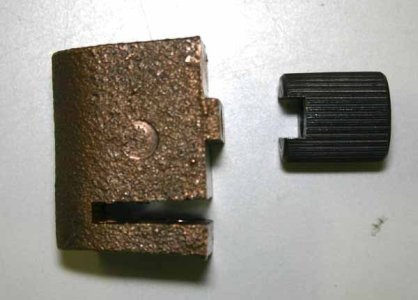
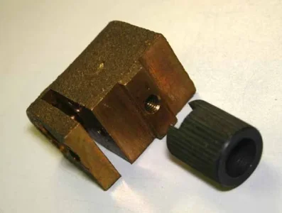
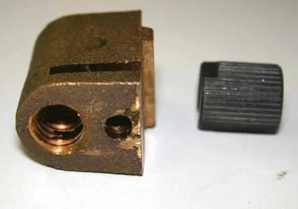
Here are the parts I was mentioning in post #6. (I ordered them as spares, I didn't remove them). Its a bit clearer to me now, but still not 100%. The steel plug has spline serrations so guessing is a press fit into the table hole. It has a groove that engages a matching raised boss on the top of the bronze lead screw nut & held captive with a cap screw. The fit is particularly tight although that might just may be typical rough tolerance? I say that because when I loosen the bolt on my lathe now, the nut becomes free (or did I push it down a bit to disengage... now I cant recall).
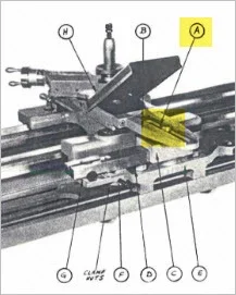
Anyway thinking out loud here - if the plug were somehow removable or even 'raise-able' so the table would slide over the nut without interference, that would allow the table to be guided with a taper bar assembly. After that, reposition the table hole over the nut & re-engage bolt to lock it down again. There must be something I'm missing, it couldn't be that easy. Otherwise why the telescoping lead screw stuff?
John, try the mod on your lathe first 🙂