• Spring 2024 meetup in Calgary - tentative date Saturday, April 20/2024. Other regions are also discussing meet ups. If you want one in your area get going on organizing it! discussion
  • We are having email/registration problems again. Diagnosis is underway. New users sorry if you are having trouble getting registered. We are exploring different options to get registered. Contact the forum via another member or on facebook if you're stuck. Update -> we think it is fixed. Let us know if not.
  • Spring meet up in Ontario, April 6/2024. NEW LOCATION See Post #31 Discussion NEW LOCATION

Are gears with the same Diametral Pitch (DP) guranteed to mesh?

RobinHood

Ultra Member
Premium Member
Thanks for all the info/links @Mcgyver! Appreciate it.

We are going to do some measuring today to see what we have. This gear turns at ~2 RPM max (usually slower); if we have the center distance so that there is some backlash, a mismatch of PA could still work, no?
 

Mcgyver

Ultra Member
if we have the center distance so that there is some backlash, a mismatch of PA could still work, no?

I'd be misrepresenting my level of gear expertise to definitely answer that. :) Probably? The involute form of course lets the teeth role off one another so you get smooth motion. You'd lose that which will make it run rough/wear more quickly if it will fit. I have noticed that with a gear tooth gauge (Boston, style with all the leaves) there's a noticeable difference between how deep the right PA gauge meshes vs the wrong one on a gear....that was the basis of my comment.....that, if a fixed distance, makes me think they wouldn't mesh. Moving them apart to make up for that would increase the running issues.

I would try and identify exactly what the PA angle is and then make or order one. If its a stock one from say Boston gear, face and bore to size and you know it'll work. I know we like to make instead of buy but last few times I needed one it seemed well worth it to save the time (if its a stock gear)
 
Last edited:

Johnwa

Ultra Member
When I tried to identify the PA in my SM gearbox I found that the measuring accuracy required was beyond my capability. Given that gear cutters cover a range of teeth numbers there is going to be some tolerance anyway.
 

RobinHood

Ultra Member
Premium Member
“What PA are your headstock drive gears? We pulled the idler gear from @RobinHood's SM and it meshed perfectly with my shaper gear. Rudy is pretty sure it's 14.5.”

So I found the answer from my SM 1340 manual provided by SM to me based on my lathe’s serial number: all the gears in the drive train to the Norton QCGB have a PA of 14.5*.

A63FB031-DCF9-4BC2-865A-2DC2C8D59F68.jpeg

It is a bit faint, but inside the 45T gear are it’s specs: “45T, 16DP, 14.5* PA”.

Here is the method we used to determine the specifications of the 14T Craig has on his shaper.

The DP is 16, no question at all. It was calculated based on the OD and the number of teeth N. It was also confirmed with a Fowler Gear Pitch gage (made in Japan) and by meshing it with the 60T gear from my SM1340 (the 60T was easiest to remove from the stack, otherwise we would have used the 45T one).

Now the PA. We tried using the method as suggested by @Mcgyver. Unfortunately, the gear tooth angle is too large to measure across 4 teeth. The measuring instrument touches the gear tooth top edges and not the flanks. So that method was out. I don’t have a comparator. So we used the 60T gear off the lathe and compared how deep the teeth meshed between the 14T, the 60T and the factory 24T on the lathe itself. The depth was identical. Plus the little 14T gear rolls around the 60T gear beautifully.

Based on the above physical experiment, we concluded that the PA is 14.5* with a very high probability.

We are collaborating on making a 28T gear that Craig needs.

He will most likely document that for us.
 

Brent H

Ultra Member
@YYCHM - from what I can tell, my main bull gear is 20 PA (72 tooth) driven by a 14 tooth gear. It is a 12 DP gear combo. I have a 12 DP 20 PA gear hobb that matches perfectly. Other gears on the feed speed are 14.5 PA and match cutter profile.
Looking at the profile of the tooth, a 20 PA tooth will be more triangular than a 14.5 PA, but it can be difficult to tell. The teeth on the drive gears on the back of the lathe I believe are 14 DP 20PA.
I think the 20 PA has a slightly larger root width on each tooth for more strength- so application suits the pressure angle.

Driving a 20 PA with a 14.5 would work, but the contact surfaces will of course be slightly off. Slow speed - probably not bad, higher speeds - not a good idea.
 

YYCHM

(Craig)
Premium Member
So with @RobinHood 's help I'm going to make my first gear. :cool:

GearBlankSetup.JPG

Here I'm setting up to face off and drill a 1/2" hole through the gear blank. That's 2" round stock and the width needs to be reduced to 0.432".

GearBlank.JPG

And all done with the gear blank for now. I'll turn it down to 1.88" OD once it's mounted on it's arbor which I'll make next.

This is going to be fun..... I get to drive Rudy's Bridgeport again:D

EDIT: Had to revisit this. Rudy tells me drilling the 1/2" hole really wasn't good enough, I needed to bore it out slightly in order to obtain a nice round hole, so I did.
 
Last edited:

YYCHM

(Craig)
Premium Member
Setting up to make the arbor now.... 3/4" round stock.

ArborSetup.JPG

Turning between centers gives me my best shot at having the arbor shank and gear blank step concentric. Also allows me to test fit the step dia in order to get it just right. I need to turn down about 6" to just a tad over 0.5". Then I will need to thread most of the step to 1/2-13.
 

kevin.decelles

Jack of all trades -- Master of none
Premium Member
Following this closely Craig, looking for good pics/description of the arbor fitment to the blank


Sent from my iPad using Tapatalk
 

Tom O

Ultra Member
Hey Craig here’s something you could use I got on eBay a few years age ( bought as hmmm one day )

1FE073B0-775F-4A76-8B92-9C16957AFB9A.jpeg

DB2ABC43-DFA3-4A9F-A7A4-8318A130033A.jpeg

EDA264D3-1BA0-4D7A-BFBE-FF7162B8FBDA.jpeg

I also have 14.5 and 20* gauges.
5EEE1535-6081-4D17-ADD9-2E150F975F9D.jpeg

I was thinking of using these mandrels.

2D5F3988-8842-426E-8C32-5E102781CC33.jpeg
 

YYCHM

(Craig)
Premium Member
So I guess what I've been calling an Arbor is actually a Mandrel....:oops:

Skim.JPG

Taking a 0.01" skim cut off the whole thing.

Step.JPG

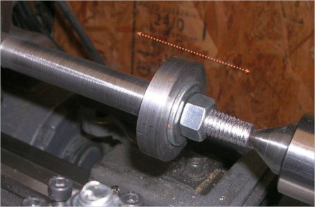
Turning the step to fit the gear blank... This is where things kind of went south on me. I could get the step to start entering the blank from one direction but it wasn't going to pass through. From this I concluded that the bore in the blank was tapered so I re-bored the tight side of the blank just a wee bit. Bingo she slid right on but the fit was a bit on the loose side now.

Step2.JPG

So time to re-turn the step. I had the new step almost entering the blank and switched to polishing it with emery cloth. Finally she would go on 1/2 way and then hang up. So now what's going on? Much head scratching..... Turning it down isn't the solution, must be something with the blank bore still. Looking at the blank bore sure as heck there was a big burr 1/2 way in.

GoodFit.JPG

After knocking that burr off with a stone she slid right on snug as could be. Phew......

Threaded.JPG

Next I threaded the Mandrel to 1/2-13. Gee that's an ugly threading job but it's functional.

TurnOD (2).JPG

Final operation is to turn the gear blank OD to 1.88"
 
Last edited:

PeterT

Ultra Member
Premium Member
Following along. Just curious why you need so much mandrel length on the left side. Wont the gear cutter just be traversing a short distance? Or maybe you are chucking that side in a 4-jaw in the mill?

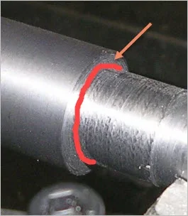
Also not sure where your burr was but another technique on these assemblies is feed a parting blade along your step taking a small finish pass off & slightly deeper into the OD. This simultaneously squares the step face relative to axis & the relief allows a sharp edge blank bore to butt up to the face without interference. A small radius on your cutting tool means you also have that radius at the base of the step & that's what the gear blank will see first, not the step. The other option is chamfer the gear blank so it doesn't interfere. But on some operations you may not want to that that quite yet.

Will this gear have a key slot too?
 

Attachments

  • 2021-05-04_23-13-38.jpg
    2021-05-04_23-13-38.jpg
    85.9 KB · Views: 7
  • 2021-05-04_23-17-54.jpg
    2021-05-04_23-17-54.jpg
    18.7 KB · Views: 7

YYCHM

(Craig)
Premium Member
Following along. Just curious why you need so much mandrel length on the left side. Wont the gear cutter just be traversing a short distance? Or maybe you are chucking that side in a 4-jaw in the mill?

Also not sure where your burr was but another technique on these assemblies is feed a parting blade along your step taking a small finish pass off & slightly deeper into the OD. This simultaneously squares the step face relative to axis & the relief allows a sharp edge blank bore to butt up to the face without interference. A small radius on your cutting tool means you also have that radius at the base of the step & that's what the gear blank will see first, not the step. The other option is chamfer the gear blank so it doesn't interfere. But on some operations you may not want to that that quite yet.

Will this gear have a key slot too?

The left side of the Mandrel is long because I don't know how long it needs to be. I think it's going in a 4J mounted on a divining head. We can always cut it down if it's a problem.

And yes, I have discovered that the blank isn't actually fully seated on the shoulder of the Mandrel, I need to add that relief cut you mentioned. I've also discovered that the washer under the nut isn't laying flat on the blank. Bent washer perhaps? I'll be looking at correcting these issues today.

Once the teeth are cut, the gear will need to be bored out to 3/4 and a keyway added. I'll add the keyway with the shaper.
 
Last edited:

francist

Super User
I’ve always bored or reamed to the finish diameter before cutting the teeth. I find trying to hang onto the gear with teeth afterwards is hard to get it concentric, plus the risk of buggering up the freshly cut teeth. There’s always multiple ways to do things though.

Good plan on keeping the mandrel stock long, I’m always just on the edge after underestimating how much clearance and over-run on either side that the gear cutter needs.

-frank
 

YYCHM

(Craig)
Premium Member
I’ve always bored or reamed to the finish diameter before cutting the teeth. I find trying to hang onto the gear with teeth afterwards is hard to get it concentric, plus the risk of buggering up the freshly cut teeth. There’s always multiple ways to do things though.

Good plan on keeping the mandrel stock long, I’m always just on the edge after underestimating how much clearance and over-run on either side that the gear cutter needs.

-frank

Ya, I'm thinking clamp it down to the mill, find center, and use a boring head to go to 3/4" might be a plan? Reaming might be in order to.
 

Brent H

Ultra Member
Hey @YYCHM I agree with @francist as far as the steps go. I have several Mandrels made up for shafts - 1/2”, 5/8 and 3/4 and all are right to size. Bore the gear blank and then ream final few thousand. Fit on the mandrel and cut your gear teeth.
If you have a big gear with lots of teeth (like 40 plus) it can take a while to make the teeth. Really sucks if you overshoot your bore afterwards- just saying.
 
Top