-
Scam Alert. Members are reminded to NOT send money to buy anything. Don't buy things remote and have it shipped - go get it yourself, pay in person, and take your equipment with you. Scammers have burned people on this forum. Urgency, secrecy, excuses, selling for friend, newish members, FUD, are RED FLAGS. A video conference call is not adequate assurance. Face to face interactions are required. Please report suspicions to the forum admins. Stay Safe - anyone can get scammed.
-
Several Regions have held meetups already, but others are being planned or are evaluating the interest. The Calgary Area Meetup is set for Saturday July 12th at 10am. The signup thread is here! Arbutus has also explored interest in a Fraser Valley meetup but it seems members either missed his thread or had other plans. Let him know if you are interested in a meetup later in the year by posting here! Slowpoke is trying to pull together an Ottawa area meetup later this summer. No date has been selected yet, so let him know if you are interested here! We are not aware of any other meetups being planned this year. If you are interested in doing something in your area, let everyone know and make it happen! Meetups are a great way to make new machining friends and get hands on help in your area. Don’t be shy, sign up and come, or plan your own meetup!
You are using an out of date browser. It may not display this or other websites correctly.
You should upgrade or use an alternative browser.
You should upgrade or use an alternative browser.
Arduino - First Light
- Thread starter Susquatch
- Start date
Which nano do you have?
Which nano do you have?
I believe it is this one.
#1 Electronic Online Store Canada For Hobby And Education
The Electronic Online Store Canada for hobby and education. We have all the electronic modules and DIY kits for Arduino, ESP32 and more.
It has a USB-C port on it.
I am
Also using the screw terminal board for convenient pin access.

 universal-solder.ca
Which nano do you have?
Also using the screw terminal board for convenient pin access.

Arduino Nano Screw Terminal Adapter
CANADUINO® Screw Terminal Adapter for Arduino Nano Development Module
This is the perfect case for the 16x2 lcd display, and the nano screw terminal board fits nicely. The only tricky bit is the orientation of the I2C leads on the display need to be perpendicular to the board.Thanks @whydontu, you also read my mind by providing the links to the documentation. And yes, I'll be using the serial data adapter. In fact, I already soldered it to the back of the LCD.
Btw, what project boxes do you like? I plan to sit it on top of the gearbox on my lathe until I get a DRO for it. Then it will move to my surface grinder.
For my original tach, I bolted a hard drive magnet to the bottom of the case to keep it in place on my lathe gear cover

For more involved builds I use these with a blank cover plate
Perfect. Thank you!
I never considered using an outdoor wall box! I was thinking bigger than that. But why? It's just some teeny tiny boards! Maybe I was just subconsciously worried about getting big hands in there.
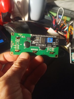
I confess that I don't understand this point. Was I supposed to put the I2C board on the display side of the display board? I put it on the back....... Does it matter? The pins all go in the same solder holes either way. Or maybe I just think they do..... Oh oh.
I never considered using an outdoor wall box! I was thinking bigger than that. But why? It's just some teeny tiny boards! Maybe I was just subconsciously worried about getting big hands in there.
The only tricky bit is the orientation of the I2C leads on the display need to be perpendicular to the board.
I confess that I don't understand this point. Was I supposed to put the I2C board on the display side of the display board? I put it on the back....... Does it matter? The pins all go in the same solder holes either way. Or maybe I just think they do..... Oh oh.
It should look like this, I buy the displays with pre-installed i2c boards (the cost from china is about the same vs buying both boards seperate)
View attachment 27029View attachment 27030
Thanks for that. That's the way mine look too.
I sorta like buying here. I get my order almost right away and the soldering is no big deal. I don't buy enough to be real concerned about the cost. The stuff is basically dirt cheap for what you get.
Thanks for that. That's the way mine look too.
I sorta like buying here. I get my order almost right away and the soldering is no big deal. I don't buy enough to be real concerned about the cost. The stuff is basically dirt cheap for what you get.
ive bought a few here as well, i agree getting it right away is sometimes worth that extra few bucks
although china is cheaper....im not sure i save any money, instead of buying just the one i need, i buy 5 and put 4 in a drawer to collect dust...because you know "they are so cheap" lol
the smaller case is quite close to the length of the 16x2 LCD. The typical I2C module has the four input pin parallel to the board. By the time you allow for the mating female wiring connector, it’s too wide to fit in the case. I try to get the modules without pins, or carefully bend the pins so the connector is perpendicular.Perfect. Thank you!
I never considered using an outdoor wall box! I was thinking bigger than that. But why? It's just some teeny tiny boards! Maybe I was just subconsciously worried about getting big hands in there.
I confess that I don't understand this point. Was I supposed to put the I2C board on the display side of the display board? I put it on the back....... Does it matter? The pins all go in the same solder holes either way. Or maybe I just think they do..... Oh oh.
#1 Electronic Online Store Canada For Hobby And Education
The Electronic Online Store Canada for hobby and education. We have all the electronic modules and DIY kits for Arduino, ESP32 and more.
the smaller case is quite close to the length of the 16x2 LCD. The typical I2C module has the four input pin parallel to the board. By the time you allow for the mating female wiring connector, it’s too wide to fit in the case. I try to get the modules without pins, or carefully bend the pins so the connector is perpendicular.
Ah, I see now. For some reason, my head was locked onto a display side issue. But it's really the overall length.
I wonder if the connections could be unsoldered and redone......
But your approach is probably easier. If you can hold them one by one in a set of pliers that leaves the board floating in the air, you can probably put a right hand bend into all four of them with another pair of pliers.
No idea how many others have encountered this, but just in case.....
I hooked up my blue 1602 LCD Display and wired it up. Then I wrote a short program to write to it.
It compiled ok and uploaded ok. But,...... It didn't work. Nothing but a blank screen.
I immediately began cursing about the lack of a debugging capability. None being readily available I started looking for possible explanations. The most obvious being a poor connection - all good. Wrong connections - all good.
Just for sh%t's n giggles I tried turning down the brightness.
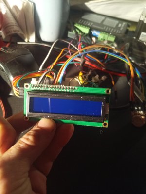
Woah! What are those really dimm letters? Turned down the brightness some more and VOILA!

The camera over saturates so here is a compensated photo.

I hooked up my blue 1602 LCD Display and wired it up. Then I wrote a short program to write to it.
It compiled ok and uploaded ok. But,...... It didn't work. Nothing but a blank screen.
I immediately began cursing about the lack of a debugging capability. None being readily available I started looking for possible explanations. The most obvious being a poor connection - all good. Wrong connections - all good.
Just for sh%t's n giggles I tried turning down the brightness.
Woah! What are those really dimm letters? Turned down the brightness some more and VOILA!
The camera over saturates so here is a compensated photo.
Take a closer look at the data sheet for your display. They tend to have an input that adjusts contrast.
Quite often marked Vee.
See the lcd display section here:
Click on the green box of the display section and you will get a pdf of the lcd interface section.
might help
Edit: Noticed your I2C driver has a contrast adjustment. Adjust that so the black behind the characters vanishes.
Quite often marked Vee.
See the lcd display section here:
Click on the green box of the display section and you will get a pdf of the lcd interface section.
might help
Edit: Noticed your I2C driver has a contrast adjustment. Adjust that so the black behind the characters vanishes.
Last edited:
That's exactly what I did to take the top photo. But then the camera oversaturates and you can't read it in the photo. In person, it looks just fine.Noticed your I2C driver has a contrast adjustment. Adjust that so the black behind the characters vanishes.
In the bottom photo I deliberately undersaturated the photo to be able to read the display. But that left the black boxes where the character matrix is.
In person, the display looks just great. The only reason for the post is in case someone else sets up an LCD display that doesn't appear to work. All it takes is to turn the pot on the back of the LCD.
Edit - if I zoom in on the display with the camera, it automatically adjusts the settings so the display looks great. I think the problem with the camera is the brightness of the LCD vs the rest of the scene.
The phone camera has a manual mode that can be used to adjust settings when the overall scene is very different from what you want the picture to show. For example a face with the sun in the background. You can move in till the face is the majority of the screen, lock the settings, then go back to where you want to take the photo from and take the shot.
Last edited:


