• Scam Alert. Members are reminded to NOT send money to buy anything. Don't buy things remote and have it shipped - go get it yourself, pay in person, and take your equipment with you. Scammers have burned people on this forum. Urgency, secrecy, excuses, selling for friend, newish members, FUD, are RED FLAGS. A video conference call is not adequate assurance. Face to face interactions are required. Please report suspicions to the forum admins. Stay Safe - anyone can get scammed.

Any solutions to my problem?

DPittman

Ultra Member
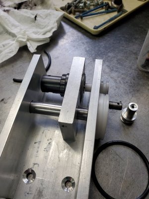
So I've been adapting an ancient old sewing machine from a clutch driven motor to a variable speed dc motor I salvaged from a treadmill. I want to use a foot driven potentiometer as the speed control. The original treadmill had a finger controlled potentiometer. I think I've got the basic mechanism figured out for the foot pedal to operate a crank which then in turn is suppose to operate the potentiometer.
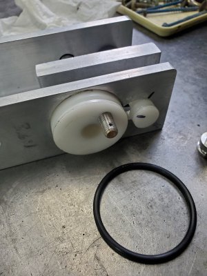
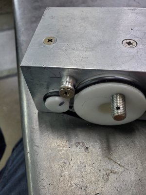
My first attempt was using gears (salvaged from an old drill) but the flex in the potentiometer shaft caused binding of the gears. After much frigging around I finally abandoned that idea and decided to try to make a belt driven wheel work in my contraption. Given the size and format of the overall foot operated mechanism I started with my wheels could only be a certain size. The wheel on the potentiometer is very small and doesn't have enough friction for the oring belt to provide consistent turning of the potentiometer. I used nylon for the gears. I've turned out a another small gear for the pot out of aluminum hoping that is would be less slippery than nylon but haven't tried that yet and do not have much hope for that either.
I think I'm probably going to have to go back to the drawing board. Part of my troubles is that I don't actually do any drawing but make up things as I go along trying to use materials and supplies I have on hand.
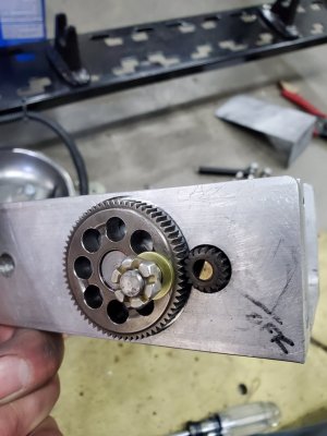
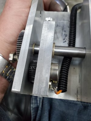
20220905_100044.jpg20220905_100051.jpg20220907_160228.jpg20220907_160222.jpg
 
The only thing I can think of right now is adding some idler pulleys in the spots where the arrows point to increase belt tension on the little wheel. Part of the problem is the potentiometer isn't real smooth operating and has a rougher spot in its rotation. (New potentiometer too)
20220907_163605.jpg
 
Toothed belt pulleys?
Yup that would have worked but I would have to have planned that I the beginning. I have a few small toothed belts but not of proper length and I am not up to (yet anyhow) making toothed pulleys.

I could make oring belts and oring pulleys so that what I did. :confused:
 
I am working on this same thing (actually it's on hold while I move) for mating a treadmill motor to a potter's wheel. In my case I'm using a MC2100 style controller and the pot was going to be part of the PWM board that drives that. I my first try was to modify the electronic (SCR type) controller in the original sewing machine foot pedal so that the existing variable resistor was used in my own PWM circuit and the rest of the original sewing machine control circuit discarded. I may still be able to do this, but the linear slider on that pot is exposed, delicate and it is a bear to put the pedal back together without damaging it.

Plan B is to put a small plastic gear on a regular rotary shaft pot, and attach a matching rack to the pedal itself to turn the gear.

Something like this:

Pots I've used historically have a 1/4" shaft. These gears look to have probably a 1mm shaft, so I'd need to adapt those somehow.

You should be able to use gears. I can't think of any good reason for there to be flex in the pot shaft. Belts (unless toothed) can slip, gears don't. If your gears are binding I would suspect something else - does the pot turn smoothly and work as expected when operated manually?
 
The little consew servo motors have a spring loaded lever for foot operation, works by draging a hall sensor across a rare earth magnet. The hall sensor of course varies its resistance as it moves across the magnetic field. I put a switch in and added a pot so I could have both control options....but their hall sense idea might be an easy way to vary resistance with minimal moving parts. I just have a rod connected to the lever with hinged bit of metal at the bottom as a pedal. Its how power watchmakers lathes, which would be a real pita without foot control

MWZ_3790-1500x998.JPG
 
The little consew servo motors have a spring loaded lever for foot operation, works by draging a hall sensor across a rare earth magnet. The hall sensor of course varies its resistance as it moves across the magnetic field. I put a switch in and added a pot so I could have both control options....but their hall sense idea might be an easy way to vary resistance with minimal moving parts. I just have a rod connected to the lever with hinged bit of metal at the bottom as a pedal. Its how power watchmakers lathes, which would be a real pita without foot control

View attachment 26299
Hmmn I have to think that one out, I don't quite understand that yet but my brain is getting tired.

I tried an idler pulley to increase tension and have come to realize tension is likely the problem actually. I don't think the potentiometer was designed to have that sort of load on the little shaft. The potentiometer seems smooth when I rotate by hand but gets a rough spot in it when the belt is on.
 

Attachments

  • 20220907_182305.jpg
    20220907_182305.jpg
    443 KB · Views: 1
A belt will put a side load on the pot shaft. If you are able to use a gear of any sort, that should be pretty strictly a rotating load.
I have used hall sensors in a "pulse every time the shaft comes around" scenario, to count rpm. I don't know if the output from one would be sufficiently linear to use directly as desired here unless it was specifically designed for that. What sort of electronics are downstream from the hall sensor?
 
I wish that would work, but they are designed for an ac motor and what I have is a dc motor that works with a controller board and a potentiometer
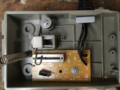
Most 'modern' (i.e. in the past 30-40 yrs) household sewing machines have 'electronic' controls and some of the foot pedals have a pot (vs a rheostat) inside. A bit of re-wiring might be required, since the connections are often to only two terminals, but the mechanical system is pretty well worked out. A trip to the thrift store can usually turn up pedals for experiments. A guitar/keyboard pedal is more expensive, but might have a ready-to-go linkage.
mini-IMG_1066.JPG

You didn't want to use a 'drop in' brushless motor replacement? They are pretty cheap - folks are buying Consew or Vevor sewing machine setups to power lathes.
 
If you can make the existing variable resistor work, that's definitely the first choice. You can usually alter your circuitry to use whatever value that resistance happens to be without much trouble.
 
You didn't want to use a 'drop in' brushless motor replacement? They are pretty cheap - folks are buying Consew or Vevor sewing machine setups to power lathes.
Yes I looked into that but did not want (couldn't) spend the money on it. I had the treadmill parts for free and thought I could make it work. I've got everything working nice but the foot controlled speed gizmo is crucial and my attempt has been a disaster. Good thing my time ain't worth anything:(
 
Most 'modern' (i.e. in the past 30-40 yrs) household sewing machines have 'electronic' controls and some of the foot pedals have a pot (vs a rheostat) inside. A bit of re-wiring might be required, since the connections are often to only two terminals, but the mechanical system is pretty well worked out. A trip to the thrift store can usually turn up pedals for experiments. A guitar/keyboard pedal is more expensive, but might have a ready-to-go linkage.
View attachment 26301

You didn't want to use a 'drop in' brushless motor replacement? They are pretty cheap - folks are buying Consew or Vevor sewing machine setups to power lathes.
Is that a guitar foot pedal?
 
Is that a guitar foot pedal?
No, it's a generic 'electronic' sewing machine pedal - $20-25 or so from amazon, and a few dollars at the thrift store if they have one. Some of the pedals just have the resistor and low power circuitry - look for a 1/8 phone type connector
 
Last edited:
Why not make a shaft extender for the pot that then rides in a bushing opposite the pot. Now you won't be pulling on the pot in a way that causes it to bind.
Or maybe even two bearings with the gear or pulley between them. Then all the load is handled by the bushings or bearings. The pot can even be coupled with a piece of plastic hose to avoid stressing the bushing in it.
 
No, it's a generic 'electronic' sewing machine pedal - $20-25 or so from amazon, and a few dollars at the thrift store if they have one. Some of the pedals just have the resistor and low power circuitry - look for a 1/8 phone type connector
Hmnn I'll look into that but I have to have a 3 wire potentiometer and I'm not sure how I would make that 2 wire one work?
 
Last edited:
Why not make a shaft extender for the pot that then rides in a bushing opposite the pot. Now you won't be pulling on the pot in a way that causes it to bind.
Or maybe even two bearings with the gear or pulley between them. Then all the load is handled by the bushings or bearings. The pot can even be coupled with a piece of plastic hose to avoid stressing the bushing in it.
Yup I should have done that.
I spent so dang much time figuring out how to make a crank arm and crank shaft to work with the original big mounted pedal on this machine and wanted to reuse the treadmill potentiometer.
Man if I could easily use a cheap sewing machine pedal easily with my existing controller board I would have to swallow my pride and throw my work on top of the scrap pile.
 
Hmnn I'll look into that but I have to have a 3 wire potentiometer and I'm it sure how I would make that 2 wire one work?
I'm pretty sure the component in the circuit board is a basic sliding pot. BTW, I've seen sewing machine pedals that do rotate the shaft of a rotary pot - one way to organize that is with a sliding (vertical) rack in a channel and pinion on the pot shaft. Lots of interesting variants...One of my sometimes hobbies is sewing machines. :)
 
Back
Top