• Scam Alert. Members are reminded to NOT send money to buy anything. Don't buy things remote and have it shipped - go get it yourself, pay in person, and take your equipment with you. Scammers have burned people on this forum. Urgency, secrecy, excuses, selling for friend, newish members, FUD, are RED FLAGS. A video conference call is not adequate assurance. Face to face interactions are required. Please report suspicions to the forum admins. Stay Safe - anyone can get scammed.

Tips/Techniques Another way to make a surface grinder balancing ring

Tips/Techniques
another notion that would sort of eliminate the flying screw issue and possibly facilitate the balancing object of the whole issue is to use pieces of appropriate length threaded ready rod tightened into the ring (think of "stud style") and then use pinch locking nuts threaded onto the studs to where they need to be to balance...changeable weights more or less.
 
I didn't realize that the holes were drilled all the way through. For some reason I thought they were blind holes. Why not use tapered machine screws?

I think there is only 4 reasons: cost, in stock here, availability when I run out, and likelihood of using them for other purposes. LOL!

But it's another good idea. If I were making them to sell, I'd definitely consider supplying them with tapered screws and call it done.

I've no interest in doing that and besides, I think the ones they are modelled after are still under patent.
 
another notion that would sort of eliminate the flying screw issue and possibly facilitate the balancing object of the whole issue is to use pieces of appropriate length threaded ready rod tightened into the ring (think of "stud style") and then use pinch locking nuts threaded onto the studs to where they need to be to balance...changeable weights more or less.

I actually considered that when I was looking at balancing a badly imbalanced grinding wheel. It would have required more than 8 screws so I considered adding nuts to every other one. Nuts don't fit on every one.

But @thestelster put that idea to bed by suggesting I shoud just junk the wheel instead....

I am going to do just that, but first I want to use it to try using steel epoxy just to evaluate the process. If that works, I may use it on some of my other wheels instead of making more balance rings. My thoughts are to use the two rings on my most popular wheels, and use epoxy on the others. Of course, that assumes it is easier to fine tune the rings than the epoxy on an ongoing basis. We will see shortly.
 
Another youtube star is born. Nice video. Clear and concise. You're pretty articulate for a forest dweller.....

A small dab of Loctite will prevent those screws from going anywhere. Then again, the act of balancing the hub in the first place will quell a lot of concerns about them walking out to begin with. Sort of a self solving problem.
 
Eagerly awaiting the epoxy trial, especially since dynamic balance is preferable to static balance and the balance rings are axially displaced from the balance problem. I have not used plastic steel when balancing and am a little concerned that it may have less tendency to flow into the porosity of the wheel than unfilled epoxy. Unfilled epoxy on both sides of the wheel bonds well and is easily adjusted with a dremel tool in very small amounts compared to the weight of a set screw.
 
Eagerly awaiting the epoxy trial, especially since dynamic balance is preferable to static balance and the balance rings are axially displaced from the balance problem. I have not used plastic steel when balancing and am a little concerned that it may have less tendency to flow into the porosity of the wheel than unfilled epoxy. Unfilled epoxy on both sides of the wheel bonds well and is easily adjusted with a dremel tool in very small amounts compared to the weight of a set screw.

Yes, I recall your earlier advice well.

I have no concerns about steel epoxy. It doesn't have pieces of steel or even fibres in it. Just tiny granules. I find it seeps into pores very easily. I am a big fan of steel epoxy. I use it all the time and have a very good feel for its uses and limits. I'd be shocked if it ever came off or didn't bond. But I will never say never either.

I plan to wipe a patch onto both sides a little heavier than whatever I think I need.

I guess we will see!
 
I was curious how much the COM was moving by filling or blanking holes. Just a bogus example. OD=2.0", ID=1.0", T=0.3" 12 possible .250" dia holes = 30 deg spacing.
This configuration blanking 7 holes (or drilling 5 holes, same thing) is equivalent to COM shift of only 0.070" below center. Of course the overall weight is changing too.
I'll have to play with this some more in assembly mode, If this balances a wheel for example, makes me wonder how far out the shaft center would have to be on a perfectly uniform (but less dense) wheel material.

1699591492708.png
1699591586257.png

left = holes configuration right = no holes (blank ring)
1699591567190.png
1699591757802.png
 
I was curious how much the COM was moving by filling or blanking holes.

You routinely amaze me Peter. I had contemplated doing a manual calculation, and that led to some experiments with a single long screw and multiple nuts stuck in one of the two hub collar holes, and that led to thinking about a generic formula, and that led to laughing at myself as well as some choice 4 letter names hurled at the idiot in the mirror.

I'd have never guessed Fusion could do that.

Awesome!
 
So..... @Hacker and @historicalarms..... How would you setup to drill and tap all those radial holes?

Just asking for the learning. I'm sure it's possible.
The machinist in you would probably want a more exacting hole spacing than the farmer in me would. I dont see that an exact hole spacing would be necessary because of the infinite balancing attainable with adjustable radial bolts, screws, or nuts would offer.
Starting the holes will require a center cutting end mill that will not deflect off the curvature of the ring and then finish drilling with any jobber drill that leaves enough thread meat. drill em' all then tap them...all done in just a mill vise of any kind
 
I would do it it on the mill with a dividing head.
The machinist in you would probably want a more exacting hole spacing than the farmer in me would. I dont see that an exact hole spacing would be necessary because of the infinite balancing attainable with adjustable radial bolts, screws, or nuts would offer.
Starting the holes will require a center cutting end mill that will not deflect off the curvature of the ring and then finish drilling with any jobber drill that leaves enough thread meat. drill em' all then tap them...all done in just a mill vise of any kind

The problem with either approach is holding the ring in a way that leaves access for drilling and tapping. If you hold it from the outside, you can't get a drill in there. If you hold it from the inside, you can't drill through.

Drilling axial holes is MUCH easier to do because the ring can sit perpendicular (flat) to the spindle and rigidly held by its edge.

FWIW, the farmer in me is quite happy with imperfection too. But perfection isn't that much more work and it sure makes the ballancing process a lot faster and more predictable. I suppose that's just a matter of choosing the lesser evil though.
 
Go into millturn/bar feed mode. Turn od, and ID and rough part off thickness, but not all the way to leave them in bar form while you drill the radial holes. Then take them back to the lathe and finish parting them off.

I'm not saying radial holes are better than axial, just offering the way to do it. IMO it would be MUCH faster making them like that, than one piece at a time with axial holes. Cuts down on indexing time drastically as you can get all the rings done in one index.

Depends what stock you are starting with though. Not all of us have a big chunk of AL barstock with the parts we need hiding in it. Sometime I find the parts I need in a few different shapes and sizes, so I have to do them one at a time, all by different methods. Working at home, is much different than at work lol.
 
Go into millturn/bar feed mode. Turn od, and ID and rough part off thickness, but not all the way to leave them in bar form while you drill the radial holes. Then take them back to the lathe and finish parting them off.

One problem with this is the other lathe machining required before parting. This is solvable but not ideal if the stock is removed from the lathe before reinstalling for parting and the other operations.

I'm not saying radial holes are better than axial, just offering the way to do it. IMO it would be MUCH faster making them like that, than one piece at a time with axial holes. Cuts down on indexing time drastically as you can get all the rings done in one index.

There is zero indexing required if a center mandrel is used on the rotary table. Just slip the ring over the mandrel, clamp, and go.

Depends what stock you are starting with though. Not all of us have a big chunk of AL barstock with the parts we need hiding in it. Sometime I find the parts I need in a few different shapes and sizes, so I have to do them one at a time, all by different methods. Working at home, is much different than at work lol.

That's a problem no matter what approach is chosen. In fact, that was the main reason for the difference between what @thestelster did and what I did. He had flat stock, I had big bar. Without that driver, I wouldn't have even posted. So your comment is spot on!

I'd also add that your proposal wouldn't work at all with flat stock.

Another problem we have not talked about is the screw interference that results from using radial screws. As the holes converge going toward center, they will interfere with each other. I think my 18 holes was already marginal in that respect. But if the balance is close, you could always go to 12 or 10 or whatever holes.

I think the big takeaway here is that there are many ways to skin a cat. None are right or wrong. It's whatever works for you, your machines, your skills and experience, your stock, and even just your outlook on the task.
 
I think the big takeaway here is that there are many ways to skin a cat. None are right or wrong. It's whatever works for you, your machines, your skills and experience, your stock, and even just your outlook on the task.
I 100% agree. I wasn't going to post, as I really didn't want to start a long debate about the merits of each method. I just wanted to offer a different approach. I think either will work, and the idea is simple in execution. When it comes out in the wash, it doesn't matter how you get there, everybody's shop, experience and available tooling/stock are different. As you say, there is more than one way to skin a cat.....

I make stuff completely different at home, than I do at work because of available equipment and material selection. I have WAY more Fabrication tooling at home than at work, but the inverse it true about machining, although I'm slowly catching up. We finally have a nice mig welder at work, but still no aluminum capability. I bring stuff home to TIG all the time. I rarely take projects to work anymore though.

If I had to make these at home, I'd probably need to start with 4-5 peices of different sized/shape material to even get started. I would bring them all to the same size, and then start from there, but I don't have a big expansive material selection to pick through, and I damn sure am not buying anything lol. I'd cast a bunch of blanks before doing that :D
 
Last edited:
You can touch that up on a green stone and it will be good.
People often damage carbide by moving the carriage after the cut and the bit is still touching the work.
Also, use WD40 for cutting aluminum, the aluminum won't stick to the cutter with that stuff.
 
I'm not parochial on this topic. I can't see a problem without trying to solve it.

The radial setscrew retention problem is very easily solved. You can get set screws that work like Nylox nuts. they have a plastic button molded into the threads. They require surprising force to turn them (at first), but unlike Nylox nuts, they can see considerable use before the nylon stops doing its job.

For those who self-flagellate, there is another approach to finer increments for re-balancing, and allows much larger offset mass. The cost is a *LOT* more holes. A second ring of holes in (thestelster version) with a a larger diameter allows choice of radial placement, and allows a lot more set screws in @Susquatch and @thestelster version.

A compromise is to make a select few of the original, but make it, for instance, 3/8" larger in diameter, and just make the holes on a larger radius. As @Susquatch said there are many ways to skin a cat (but how cruel)!!
 
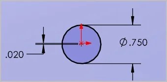
When you guys are balancing your wheels, I assume the radial hole set screw ring stays put for both the initial run in (thus dressing the wheel OD perfectly radial to the shaft center dictated by the ring/arbor) and then directly to the balancing bars for set screw adjustment? Because center of mass of the larger diameter wheel is very sensitive to the position of the shaft center. If that varies between running/dressing shaft assembly & measuring with a new shaft assembly, it adds a new repositioning variable into the mix. For example in CAD I moved the center of the axle hole only 0.020", but the C.O.M moved 0.380".

I discovered this in a more practical manner with some bench grinder wheels. The axle holes were loose & oval relative to the annular plastic spacer rings provided & those were quite loose relative to the grinder shaft. Just my loosening & tightening the nut, the wheel could displace a tiny amount & was the difference between the grinder vibrating & running smoothly. So you always had to dress the wheel with every re-mount, which is good practice anyway, but PITA if its out an appreciable amount. And just because the wheel is dimensionally round to shaft center, balance is still affected by density variations of wheel matrix (although I have no data to support it would vary much) and o lesser degree, the washer relative to shaft. On my TCG the collars stay attached to the wheel & wheel/collar assembly mounts to a tapered arbor which helps a lot with consistency swapping wheels. I'm not sure if surface grinders need even more tweaking beyond this. The thing is COM is sensitive to radius (I think its R-squared?) so bigger diameter wheels will be fussier to tune.

1699724086944.webp

1699724150533.webp
 

Attachments

  • 1699724113381.webp
    1699724113381.webp
    3.4 KB · Views: 0
Great thought. Most surface grinder wheel bores are made with far more precision than standard bench wheels. All of mine just slip on, with very low clearance -- except one, for which I had to use a paper shim while installing.

The larger SG wheels (8" and above) usually come with a plastic insert and those require a little force (or sometimes more than a little) to slip on the 1 1/4" arbour. The 10" SG at Tested Truss needed a light press to get it on the spindle adapter. It still needed balancing - the balance ring was about 4" in diameter. The ones we used, had 3 counterweights with set screws, and they did the job well.
 
Back
Top