• Spring 2024 meetup in Calgary - date Saturday, April 20/2024. discussion Please RSVP Here to confirm and get your invitation and the location details. RSVP NOW so organizers can plan to get sufficient food etc. One week to go! More info and agenda
  • We are having email/registration problems again. Diagnosis is underway. New users sorry if you are having trouble getting registered. We are exploring different options to get registered. Contact the forum via another member or on facebook if you're stuck. Update -> we think it is fixed. Let us know if not.
  • Spring meet up in Ontario, April 6/2024. NEW LOCATION See Post #31 Discussion AND THE NEW LOCATION

Another drafting question! :)

mprozycki

Member
Hey guys,

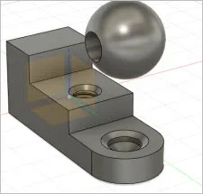
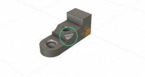
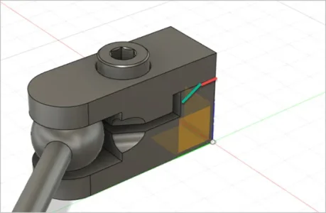
It's been a few months since I've posted but I'm nearing the point of moving forward with having a part from "Ball-Socket Joints" project CNC machined. I had some really good help from a fellow member (PeterT) with creating a clean technical drawings, which i implemented right away. I have completed the tech. drawings for the part bellow (not shown), but I recently decided to add one small detail to the joint as shown.

1_4_Joint_5a_Revise_Bot.jpg

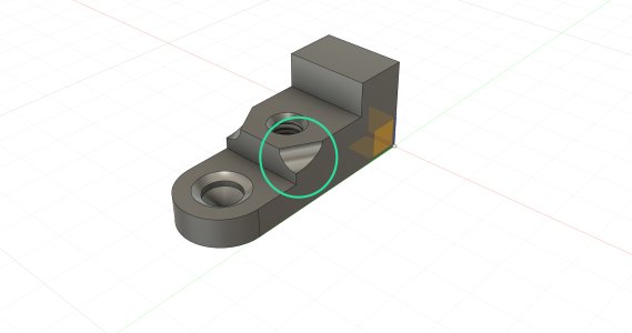
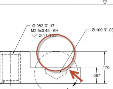
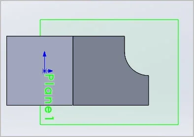
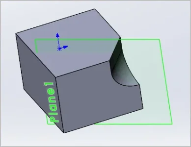
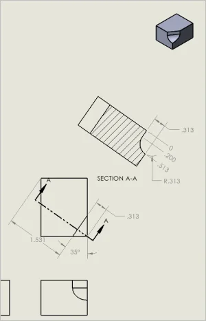
It's a slight cut on the corner of the part to allow for clearance. It's essentially a cut done with a ball-end milling moving across the piece at a 30 degree angle. However, I'm at loss as to how to describe it in terms of the tech drawing. The STEP file that I'm submitting has all the information but I'd like to also demonstrate the nature of the dimension in the drawing.

If someone could point me to a resource that discuss how to draft a complex dimension like this, I'd really appreciate it.
Or you can tell me that I'm way over my depth as a hobbyist and I'll begrudgingly opt out of the detail. Thanks for hearing me out.

P.S - Here is a quick link describing the nature of my project in a previous post.

https://canadianhobbymetalworkers.com/threads/question-regarding-coatings-on-s-s-balls.2849/
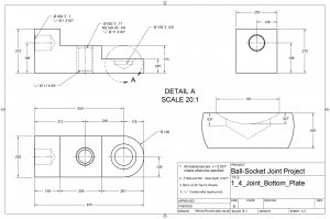
 

Attachments

  • 1_4_Joint_5a_Revise.jpg
    1_4_Joint_5a_Revise.jpg
    327.5 KB · Views: 10

PeterT

Ultra Member
Premium Member
If I understand the scallop (or maybe ball end mill?) shape correctly - I would convey the plane angle that the cut is oblique to. Then dimension the scallop cut profile on that view. So here I made a drawing section view coincident to the cut plane within the part. You also should provide a dimension of the cut profile relative to a known reference edge even if its redundant. So in this example 1.531 or 0.313 refer to the same feature, but the 1.531 is easier to measure (validate) for the machinist. You could discus this feature with the machinist in terms of tooling (cost) difference of a ball end mill making the fillet scallop vs a 45-deg insert tool making a facet. I mean if you want a curve then he will price a curve, but if its more about a chamfer reduction maybe there is a cheaper but acceptable aesthetic solution.

I didn't do the hole dimensioning but I would use the thick stair step edge as a reference surface & dimension all holes from there.

This is just general guidance because I'm not sure what must fit what or if its more cosmetic.
 

Attachments

  • SNAG-2021-07-22 11.22.29 PM.jpg
    SNAG-2021-07-22 11.22.29 PM.jpg
    15.7 KB · Views: 7
  • SNAG-2021-07-22 11.22.46 PM - Copy.jpg
    SNAG-2021-07-22 11.22.46 PM - Copy.jpg
    19.6 KB · Views: 9
  • SNAG-2021-07-22 11.39.50 PM - Copy.jpg
    SNAG-2021-07-22 11.39.50 PM - Copy.jpg
    43 KB · Views: 10

mprozycki

Member
Hi Peter. Thank you for the reply. I see! The scallop is the accurate terminology for the cut. The removal of the material will just allow clearance for a pin that's attached to the steel ball sitting in the joint seat. It could be done with files but the parts are to be CNC machined, so might as well get it done then. I'll post a few more pictures of what I mean. 1_4_Joint_5a_Revise v14.png 1_4_Joint_5a_Revise v13.png 1_4_Joint_5a_Revise v12.jpg

I guess in the end, it's not absoultey necessary to have this feature. But like I said, they're going to be done on CNC as a small batch, so I figured it would be best to include it.
 
Last edited:

PeterT

Ultra Member
Premium Member
Just as an aside, not sure if you have tested this already. But you can obtain a lot more mechanical clamping efficiency for the same cap screw tightening torque by reducing the pivot area (red). This could milled as a simple step or you could chamfer it for cosmetics (green). Better yet red area would be a convex curve profile so the contact is always a tangent line regardless & can handle ball size variation or other distortions. Flat on flat like that is requiring the balls & ball seats & clamps to be very precise & distortion free. Also the closer you move the bolt to the ball, the more clamping pressure will be applied. Looks like you have it centered but it doesn't necessarily have to be that way.
 

Attachments

  • EDT-2021-07-23 5.39.36 PM.jpg
    EDT-2021-07-23 5.39.36 PM.jpg
    27.3 KB · Views: 11
Last edited:

Janger

(John)
Administrator
Vendor
How many of those parts do you need @mprozycki ? And what material? The reason I ask is you many be able to make these parts on a manual mill just as easily. It depends on how many to a certain extent.

I agree with Peter about the hinge design. Have you made one and tested it? How is this part attached to other parts? I would make one to test as I feel torquing forces could make the two sides twist or move oddly. I'd like to know what this part is for but perhaps you don't want to talk about your full project which is understandable.
 

Janger

(John)
Administrator
Vendor
Oh I see what you are up to. My comments on testing were assuming there were significant loads on the joint in some sort of machine. I think you should 3d print those parts - I imagine it would work fine and cost far less. Also that scallop could be simply done with an end mill if you all need is some clearance for the rod.
 

mprozycki

Member
I understand. The dimensions of the joint is based on an existing design. The position of Cap screw is off centre towards the ball. When I was reproducing them in 360 Fusion, I asked why not just place it in the centre? Concluded that it would have more clamping strength on to the ball if it was closer. You just verified it! Thanks. :) This is a 1/4 ball size joint, but the larger 1/2 has a step! So another great insight into the design, Peter! Of course, this size can't have a step because it interferes with the hole for the pin. Here is an older draft of the plans for the bottom plate. They were revised with your help, of course. I'm still working on integrating the scallop into a new set of plans.
 

Attachments

  • 1_4_Joint_Bot_Revise.jpg
    1_4_Joint_Bot_Revise.jpg
    212.8 KB · Views: 5
Last edited:

mprozycki

Member
Hi John. :) Yes, I have a bunch of these parts already They're made of mild or Stainless and usually brazened with silver solder. These are ball-socket joints for a animation armature to be used for stop-motion animation or puppet animation. I've already printed of a bunch of these parts with a 3d printer as a sample, but metal is the only material that'll work. I'm outsourcing the parts to 3dHUBS to be produced on a CNC. I need 20 joints for one puppet. I've machined them by hand along time ago, but I was very young and naive so they didn't work very well. Overal, it's far more cost and time effective to get them done by CNC. Though if I had to equipment, I wouldn't hesitate to make them manually. :)
 

PeterT

Ultra Member
Premium Member
So is the ball seat a chamfer (a flat line cut rotated about hole axis) or is it a spherical profile (like a ball end mill plunging in Y-direction)
 

Attachments

  • 7-26-2021 12-18-21 PM.jpg
    7-26-2021 12-18-21 PM.jpg
    26.1 KB · Views: 2
  • 7-26-2021 12-19-57 PM.jpg
    7-26-2021 12-19-57 PM.jpg
    10.1 KB · Views: 2

mprozycki

Member
It's a curved seat created by a ball-end mill equal to the size of the ball. Though, a chamfer could also be used. The curve would develop naturally as the ball grinds away at the seat.
 
Top