Is the description of the parameters all from the manual that came with your device?
Hahahaha hahhaha You're funny Craig. Jk.
No I have the standard manual with whacked out information. Or none. I has to do so much research and take notes, and I did find a community based document at one time but it is on my old laptop. I'll have to dig it out.
I'd have preferred to upload it somewhere useful that doesn't reply on my computer.
Re P02, your chart says you set it to "N/C". Whazzat? No change?
Correct, No change.
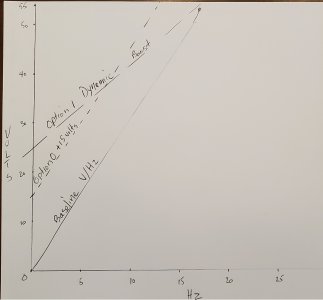
This surface grinder application operates at a constant, fixed speed, always running at the motor's rated nameplate frequency of 60 Hz, therefore the default linear voltage to frequency (V/Hz) profile is ideal.
The linear curve provides a predictable, proportional relationship between voltage and frequency as the motor ramps up and down, if I choose to use ramp down too.
While the profile has no effect once the motor reaches its steady, full speed operating state, a linear curve ensures the motor receives adequate torque to safely overcome inertia during the initial acceleration phase without triggering overcurrent faults.
Side note, I plan to use Robin Renzetti's molybdenum stick diamond and cbn wheel trueing technique. Robin achieves the 700 surface feet per minute speed by starting and stopping his grinder spindle and dressing the wheel as the wheel spins down. Precision Kinetics has a cnc grinder and just program their dressing speed. I hate them.
I am going to see what works best, inertial stopping, or a controlled ramp down. Once I'm done experimenting I'll program in the best option.
Re soft start, I'm curious if you've used the Current display mode (set P62 to 3) to see how much the motor is drawing during the 10 second start up
In the past I has used the display to review the current on our bridgeport during the initial testing and set-up process to ensure that I was not over taxing the motor. Our old lathe had new inverter duty motor so I wasn't worried about it as much as I do the bridgeport motor.
BUT instead of programming P62, whcih is a pain in the ass, I use a different technique to temporarily toggle thru the display settings while operating the VFD. Real time diagnostics can be performed instantly from the VFD faceplate during operation.
To Toggle the live display, put the VFD into its normal operating state, ready or running, and press the Function / Data button sequentially. The display will cycle through Target Frequency \ Actual Output Frequency \ Real time Amperage Draw \ VFD Internal Temperature.
Leave the display on the Amperage screen while taking a heavy manual test cut or ramping up. If the current spikes or continuously approaches the full-load amps (FLA) rating on your motor nameplate, reduce the feed rate or adjust your V/Hz curve profile.
P70, P71 and P72. I imagine you are not using these settings since you're not using variable speed. However, does your manual have a usable description of these parameters?
NOTE:
If you need serious torque compensation I recommend using the vastly superior Westinghouse L510 VFD because it utilizes microprocessors capable of advanced mathematical motor modeling, sensorless vector control and intelligent dynamic calculation for torque compensation.
BUT since I know my audience and that even some lighter duty equipment can benefit from a bit of torque compensation I'll explain this to the best of my ability while admitting that I have only played around with these settings during my education process and then restored the VFD to the defaults since I had no need for compensation on the machines I have chinese VFDs on
So...
Parameters P70, P71, and P72 are the torque compensation settings on the XSY-AT1 VFD. They are used to boost motor torque at very low speeds, aka low frequencies by artificially increasing the voltage supplied to the motor. Standard AC motors lose torque when run at low frequencies because the inherent resistance of the copper windings limits current flow. Tweaking these settings helps prevent the motor from stalling under heavy start-up loads.
Use this setting if your motor is stalling, cogging, or struggling to start moving a heavy load at low speeds (such as on a heavy bed lathe), you should adjust these values.
BUT there is also another setting that can also effect such changes. The previously mentioned V/HZ profile affected thru the P00 - P05 parameters.
It is vital to understand that modifying the V/Hz profile (P00–P05) and modifying Torque Compensation (P70–P72) are two different tools used to achieve similar goals and then decide which is the best parameter to set.
Parameters P00 through P05 define the entire permanent path of the motor's power curve from zero to maximum RPM. Shifting this line changes the core running characteristics across all frequencies.
The torque compensation parameters P70 through P72 act as a temporary low speed voltage override. They inject artificial voltage at low frequencies to overcome heavy mechanical breakaway inertia. Once the spindle is spinning and passes out of the low-frequency zone, this override tapers off, and the core V/Hz profile resumes complete control.
As a rule, modify the global V/Hz profile when the nature of the machine's load changes across its entire operating speed spectrum, e.g., how a pump or fan act vs. a spindle. The VFD defaults all assume spindle operation.
Modify the local torque boost parameters when the machine runs perfectly at normal speeds, but struggles with static breakaway inertia (start-up) or heavy loading under ~15 Hz. Basically lathes swinging large loads... or mills where you like to use face mills taking big cuts.
What each parameter means is a bitch to find out. I had to extrapolate from many sources and use manuals from westinghouse and others to see how they work to see how the knock offs are operating.
P70 simply tells the VFD which torque compensation option to use.
0 = to use value in P72,
1 = use the equation P72 x (P71 - real-time input voltage).
0 is the default.
The choice between selecting OPTION 0 or OPTION 1 for parameter P70 is VERY IMPORTANT.
P72 is a simple unitless boost gain scale from 0 to 100. This value tells the VFD to fetch a static fixed voltage value to inject from an internal look-up table, roughly ading ~5–10V to the bottom of the curve.
Crucial Warning
Do not turn P72 up too high right away. Forcing too much voltage into a slow moving motor at low frequencies causes rapid heat buildup. Because the motor's built in fan spins slowly at low speeds, a high torque boost can quickly overheat and burn out the motor windings.
Gradually increase P72.
Enter programming mode, navigate to P72, and increase it from 0 to a small number like 3, 5 or 10. Test the motor. Run your machine at a low frequency, e.g., 5 Hz to 10 Hz and see if it can handle the load without stalling. IF your motor still struggles at the selected value just select a higher number and test again... rinse, lather repeat.
BUT when you switch P70 to Option 1, and tell the VFD to use the equation
P72 x (P71 - real-time input voltage) you transform the low end torque boost from a dumb, static setting
into a dynamic, load-sensing voltage regulator.
The chart below compares the operational metrics of both torque compensation modes.
| Operational Metric | Option 0 Fixed Boost | Option 1 Dynamic Slope Modifier Equation |
What P71 does
|
Acts as a rigid voltage baseline limit.
|
Acts as a target crossover threshold.
|
| Voltage Behaviour |
The VFD injects the value of P72 as a flat, unyielding voltage offset.
| The VFD continuously recalculates the voltage delta, tapering the boost away smoothly. |
| Risk |
High Thermal Risk. The motor is continuously forced to run overfluxed across a wider band of low-RPM operation
|
Low Thermal Risk. Boost power is sharply throttled back the millisecond the motor gets through the breakaway zone.
|
P71 is the torque compensation voltage range of 0.0V to 300.0V. The default is typically 10V. This establishes the baseline voltage limit for the dynamic formula if P70 is set to 1.
In short, Option 0 injects a blunt block of extra voltage, while Option 1 creates a smooth, diagonal ramp down curve for the boost itself, matching the motor's actual electrical acceleration curve.
To implement dynamic boost successfully, try these starting values and logical guidelines for testing.
P70: Set to 1 to activate the dynamic equation.
P71: Set the voltage threshold ceiling to 15.0V, or leave at the factory default of 10.0V.
This tells the VFD to keep the dynamic boost active only until the core profile voltage climbs past this small window. Keeping this value low ensures the boost circuit completely shuts down before the motor speeds up and gets too hot.
P72: Set the unitless gain multiplier to 5 as a safe, baseline starting multiplier.
Step by step testing & tuning guidance:
Because P72 functions as an amplifier multiplier in the equation, you want to find the exact point where you have enough torque to start your heaviest workpiece or chuck without causing an overcurrent trip.
To test the baseline P72 = , mount your heaviest chuck, faceplate, or fixture. Attempt to start the machine at a low target frequency. e.g., 5 Hz to 10 Hz.
If the VFD instantly trips on overcurrent, ERR 1 your multiplier is too high, or your acceleration time (P34) is too fast.
Lower P72 to 3 and test again.
If the motor groans, stalls, or spins up too sluggishly, your multiplier is too low. The VFD is not injecting enough starting voltage to overcome the dead weight. Increase P72 to 8, then 12, then 15, re-testing after each change.
Once the machine starts successfully, use the FUNC / DATA key shortcut to toggle your screen over to the live Amperage (A) display. Watch the numbers. You should see a brief spike in amps right at a dead stop, which should rapidly drop down to a low, safe idling current within 2 to 3 seconds as the spindle gets up to speed.
I hope this is clear and self explanatory, but I'm happy to answer questions.