• Scam Alert. Members are reminded to NOT send money to buy anything. Don't buy things remote and have it shipped - go get it yourself, pay in person, and take your equipment with you. Scammers have burned people on this forum. Urgency, secrecy, excuses, selling for friend, newish members, FUD, are RED FLAGS. A video conference call is not adequate assurance. Face to face interactions are required. Please report suspicions to the forum admins. Stay Safe - anyone can get scammed.
  • The 2026 Calgary Area Meetup is set for Saturday May 30th at 10am. The signup thread is here! Robinhood has graciously offered to host the meetup again this year. Please note that you MUST RSVP to the notice linked above if you wish to come.

And this concludes one of the longest episodes in machine moving history....

TorontoBuilder

Sapientia et Doctrina Stabilitas
I wanted to give a shout out to @PatrickT but I guess he is blocking me for some reason.

I thought he'd appreciate this surface grinder he sold to us, finally moving into the right shop.

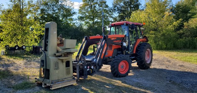
And the large hydraulic one finally getting to it's permanent home.

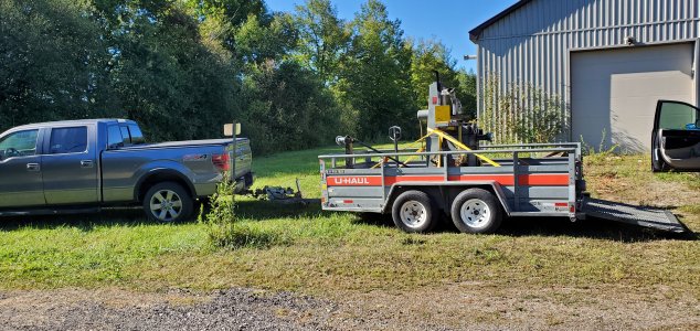
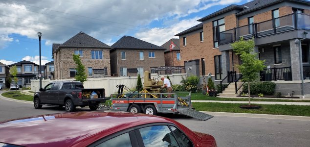
We're getting too old for this shit. Am I allowed to say shit still? Anyway loaded it up on Thursday late afternoon in anticipation of a Friday morning trek thru the hellscape that are Toronto Hwys.

1788130311225.jpeg

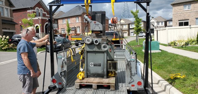
Made it across Friday morning and then the real labour began putting the gantry crane together, blocking up the trailer and back gate... then sliding grinder 1 into position.

1788130604681.jpeg

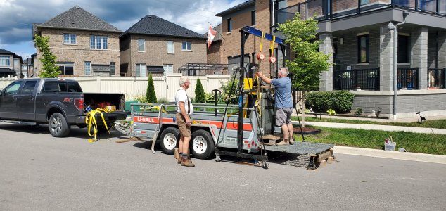
And lift with your knees, not your back.

1788130672552.jpeg


This way high noon, the sun was brutal and Tom's blood sugar went wonky so he had to check out of much of part 2. So I have less photo documentation of this part.

1788130947819.jpeg


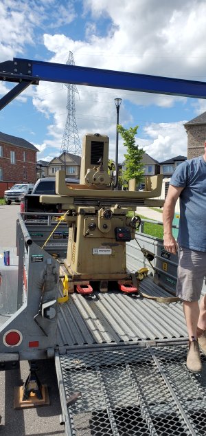
Skipping ahead, Dave and I got it loaded, no one got dead or injured other than heat stroke and bad sun burn to the back of the neck.


1788131000864.jpeg


Thank god one end of the dual trek is sophisticated.

1788130901341.jpeg


Oh and what made the move so long was the years between acquisition and actually completing the moves. It's been a year, or almost two... to be clear, a really shitty year
 
Yes, once you reach the age of 55 blundstone boots are mandatory dontcha know

After 70 you can take them off again. No feelings left in your feet.

I have not heard from Patrick either. Given what he does for a living, I'm not surprised. He could be in the Congo up to his ears in giant snakes with no phones or internet.

Not many guys can leave my wife speechless. He is missed.
 
I spent a few hours working on the Reid 618 HA surface grinder.

Removed the 6x12 chuck and installed the 6x18" chuck. To do that Tom had to mill recesses in the chuck because it came with split recesses off to the sides.

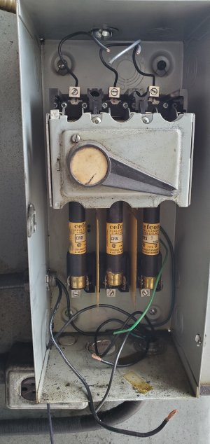
I pulled off the 600 volt main disconnect box.. stupidly over sized beast. Installed by 1970s era slotted screws, one of whihc stripped necessitating brute force removal.

1789343188876.jpeg

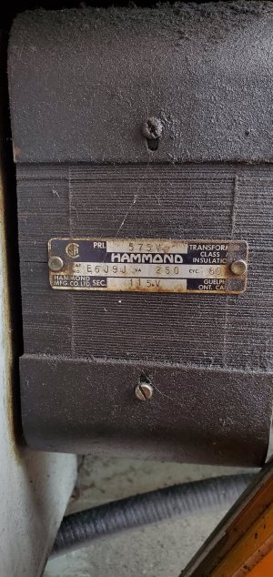
My next victim was the 575 to 120 volt hammond transformer... and electrical outlet. I feel bad not using the lovely 2x4 cast iron box.


No pic of the box, I was too greasy.

But the transformer is a hoot. I bet they never once plugged a light into the outlet.


1789343462689.jpeg


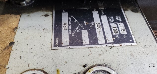
Then came the 600 volt to 480 volt transformer.

1789343594515.jpeg


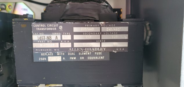
Then yet another transformer...

Just to power the 120volt coil in the contactor.

1789343862391.jpeg


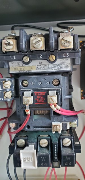
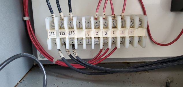
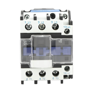
And said contactor.

State of the art baby.

1789343913652.jpeg


So.

Decisions.

Do I replace everything, or keep all this and just have the output from the motor started power the VFD.


1789345022804.jpeg


The distribution block at least should stay dontcha think?

1789345115449.jpeg


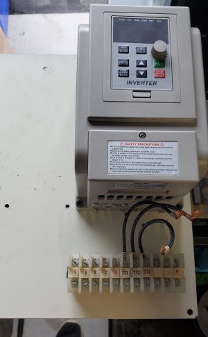
In reality, I'm going with new 240 to 24v transformer, new contactor. These will open a ton of real estate for a VFD in the sealed cabinet. Time will tell if I have over heating issues with this arrangement.

The 24 volt DC will be wired in a classic 3 wire control latching circuit. Then I'll wire the normally closed fault relay output from the VFD into this 24V latching string so that any VFD issue drops the power to the entire unit.

I can't get the half of the wheel adapter that was left on the spindle off, because I can't find the puller I had acquired with some other adapters. So I have to order one.

But hopefully I'll be grinding soon.
 
Sorry but I don't have the specs. What size/voltage motor are you going to use?

Personally, I would use the A-B contactor rather than a new one. Those things are near indestructible.

But...I could make a case that a magnetic contactor ahead of the VFD is overkill for small horsepower applications. Any decent VFD can be programmed to NOT automatically restart after a power failure. Thus if you have a simple maintained switch upstream of the VFD, nothing bad is going to happen in the classic 'power blip' scenario. A motor-rated toggle switch, possibly with pilot light, is cheap and simple. With the VFD's low voltage circuits, you can have multiple guard/safety switches and a separate Emergency Stop with max braking, as you may desire.

Also, you say " I'll wire the normally closed fault relay output from the VFD into this 24V latching string so that any VFD issue drops the power to the entire unit." I'm not sure why you want to do this? If the VFD shuts down the motor, you'll want to be able to see the fault code, no?

Just food for thought.

Craig in Oakville
(Not an electrician, yada yada.)
 
@trlvn those are good points.

Yes, I would want to see a fault code... I haven't had one while operating a machine yet, and didn't think of that.

Also, I'm cheap so I can easily be talked into keeping the A-B contactor. It's worked well for half a century. I think I can still squeeze a VFD in the cabinet
 
The results are in... the VFD wont fit with the existing over sized contactor and stupid 240 to 110 transformer.

So Out with the transformer and the contactor, in with the VFD.

I've ordered a new contactor with a nice appropriate 220V coil so I don't even need a transformer.

1789942293081.png

Had a slight set back when I went to use the lathe and discovered that my brother disconnected the power when he built a elevator on his garage wall to raise and lower his tire storage racks... I'm glad he did because I couldn't lift jeep tires up to the ceiling any more.

So the 220v outlet needs to be reconnected before the wheel remover can be made.

But almost there... I'll take any progress I can get these days

1789942599041.jpeg
 
This post is just my working notes... but could also prove beneficial to some people who wish to better understand how their VFD works and get a better set up.

My Reid surface grinder uses an integral motorized cartridge spindle with 1 HP Whiton Motor of 3400 rpm. Replacements are basically impossible to come by, so I'll be very careful not to harm this puppy. That means understanding every parameter in the VFD setup.

Because the grinder will only be used sparingly at a single speed I'm using a cheap Chinese VFD model XSY-AT1.

Here is how I will program it.
1 (Potentiometer)1 (or 0 for keys)Uses the onboard dial knob to alter speed manual ranges.

ParameterMeaningFactory DefaultMy motor requirement
P00Maximum VFD Output Voltage (volts)220220 (to match my motor)
P01Reference Base Frequency (Hz) (the motors native frequency, change to NA standard)50.0 60.0
P02Intermediate Voltage (Mid-point voltage for standard linear V/Hz scaling)110N/C
P03Intermediate Frequency (Hz) (Half the Base frequency)2530
P04Minimum Voltage 0.0 0.0
P05Minimum Frequency0.00.0
P06Maximum Operating Frequency (The VFD's hard governor for calculations)6560 (3400 RPM
P07Minimum Operating Frequency (Allows full speed range down to 0)0.00.0
P10Speed Command Source (1 for Panel Potentiometer, or 0 for keys)10
P11Run / Stop Control Source (Keypad = 0 Enables the front panel RUN and STOP keys)00
P12 Stopping Modes (Inertial Stop = 0, decel =1, Brake = 2, Emerg Brake = 3)10

P04, P05, P06 & P07 apply when the VFD is actively running and you change the frequency (such as turning a rheostat/potentiometer knob down to zero).

P04 is the Minimum Voltage parameter on the XSY-AT1's linear Volts-per-Hertz (V/Hz) power curve. It works in conjunction with P05.

In the standard default with P04 = 0V and P05 = 0Hz, if you use a rheostat knob to turn the speed down while the VFD is still switched "ON," you can dial it all the way down to a dead stop (0 Hz at 0 Volts).

If P04 is set to something higher, e.g., 20V and P05 is set higher, e.g., 10Hz, when you try to dial the rheostat knob all the way down, the VFD's programming will refuse to go below that floor.

It will keep the motor it spinning at a minimum baseline of 10Hz and feeding it 20V of power, no matter how low you turn the knob.

Setting a floor using P04 and P05 is an incredibly useful trick on a variable-speed lathe or milling machine.

When using an inverter-duty motor on a lathe, an operator will frequently dial the potentiometer knob down to slow the spindle for some tasks. However, if they dial it down too close to 0 Hz, the motor will stall, lose all torque, and heat up rapidly.

By setting a floor, no matter how far or fast the operator twists the speed knob, the VFD guarantees the motor never drops into a useless, high amp stalling zone.
Even if it is an inverter-duty motor rated to handle heat better, keeping a minimum RPM floor ensures the motor's fan keeps spinning fast enough to clear out heat during extended setups.

Since I am bypassing speed variations altogether and configuring my setup as a single speed 60 Hz machine, I want P04 and P05 left at exactly 0.

Leaving them at zero ensures that when I execute a Stop command, the VFD collapses its output voltage instantly and cleanly to 0V/0Hz, allowing my Whiton spindle to transition smoothly into a free coast mode for using the molybdenum stick method of truing resin bonded diamond and cbn wheels.

While P07, the minimum operating frequency, primarily dictates the lower floor when variable speed operation is desired, I've seen this set to 60 Hz where single speed motor operation is desired. This seems logical BUT doing so can create a massive conflict if you desire to implement a soft start in the later settings.

Crucial Hardware, Safety & Carrier Settings:

ParameterMeaningFactory DefaultMy motor requirement
P18Grid Supply Frequency* (Tells the drive the frequency it's seeing on the utility mains)5060
P21Reduction Ratio (1 -100) OR It has a reference RPM at 50Hz depending on firmware11
P22Carrier Frequency (2-16 kHz)102, 3, or 4
P24Overload Protection Time (0.1 - 60 seconds ) How long the motor can exceed FLA setting P76.33 (seconds)
P25Motor Series Selection aka Pole Count ( 2 Pole = 0, 4 Pole =1, 6 pole = 2)00 (2 pole motor)
P26Working Frequency (0-400) (the VFD cruise control to cap user input)5060
However do you delete a row???
P34Main Rising Velocity (Acceleration Ramp Time aka soft-start) in Hz / second506
P62Display Options (Setting Frequency 0, Operating Frequency 1, RPM 2, Amps 3, Temp 4)04 (VFD Internal temp)
P76Current Coefficient (0-65535) This is the main current overload setting in mA (match motor FLA)95003000 (milliamps)

P18 is very important... it is like a tuning fork for tuning a piano.

Just like a piano tuner uses that 440 Hz fork as the absolute reference pitch to map out the mathematical intervals for all the other keys, the VFD uses P18 as its anchor pitch to scale the math behind its pulse width modulation output waveforms.

If you leave your piano tuning fork at 500 Hz but try to play a song written for 440 Hz, all the calculations are skewed and the music sounds wrong. By moving P18 from its factory default of 50 Hz to 60.0 Hz, you are successfully retuning the VFD's internal calculator so that its baseline logic lines up perfectly with a standard North American grid and motor profile. Basically, you're telling the VFD, the tone you're hearing via the utility mains is 60Hz not 50Hz.

P21 The reduction ratio is the motor to spindle pulley ratio, in this case 1 due to direct connection.
BUT on some VFDs this is the reference rpm at 50 hz. THIS MUST BE SET for the calculated actual RPM to display on the VFD screen correctly.

P22 The carrier frequency parameter selects the carrier frequency to find optimized carrier for the motor and VFD combination. A setting in the audible spectrum causes a motor hum, while too high cause voltage spikes, overheating of the IG** and transient spikes that cause pitting of the bearing races.

P22 Selects the switching frequency of the IGBTs to optimize the motor and VFD combination. A low setting in the audible spectrum (2–4 kHz) causes a noticeable motor hum but keeps the VFD cooler. Too high a setting (8–16 kHz) causes severe high voltage spikes, rapid overheating of the IGBTs, and high-frequency shaft currents that lead to bearing fluting aka pitting.
The default value of 10 corresponds to roughly 8–10 kHz to make the motor quiet. I must drop this frequency to protect the old Whiton motor insulation from high voltage spikes. I'll use the minimum of 2.

This forces the internal IGBT transistors to switch at a much lower frequency. This also keeps the VFD much cooler, which is also important since the VFD will be in a closed box to protect from grinding dust.

P24 and P34 operate in conjunction with each other to minimize the inrush current when the spindle motor is started. These two parameters ensure that the P76 parameter is never exceeded for a length of time that causes damage to the vintage motor insulation or trips the VFD into a fault. P24 allows over current for a brief 3 second period. P34 ramps up the motor speed to the full rpm over 10 second period (60hz divided by 6hz /second = 10 seconds.

Since VFD over heating may be an issue due to the installation in an enclosed electrical cabinet I am using several strategies to limit this potential and protect from accidentally causing an ERR 8 excessive temperature fault.

First, I've removed all unnecessary components and transformers from the electrical cabinet. The I selected the carrier frequency that produces the least amount of heat. Then finally I'll add a sight glass to the front of the panel that will allow me to view the VFD display occasionally.

By changing the display option parameter P62 to 4, the VFD faceplate stops showing Hz or RPM and explicitly displays the internal temperature of the VFD heatsink module in Celsius. I can then monitor, log and plot time/temperature curves to determine operating times to error code may occur and different ambient temperatures in the shop.

Then I still have another layer of protection with the VFD's auto-trip protection. The XSY-AT1 has programmable thermal protection thresholds built into its microprocessor. If the internal heat sink passes the upper limit of 80°C, the VFD will automatically sound a fault beep, stop the motor, and display an ERR 8 (Over-temperature/Module Protection) code to protect its internal circuitry from failure.
 
I did a similar chart while programming a Vevor VFD for use on my mill/drill. Except, you appear to have had much better documentation to work with. Is the description of the parameters all from the manual that came with your device?

Re P02, your chart says you set it to "N/C". Whazzat? No change?

Re soft start, I'm curious if you've used the Current display mode (set P62 to 3) to see how much the motor is drawing during the 10 second start up. I understand that best practice is to let a surface grinder run for several minutes in order for the bearings to come up to operating temperature before starting actual work. So the 10 s ramp time is trivial compared to that. With a mill, however, that ramp would be tediously long.

Torque compensation: P70, P71 and P72. I imagine you are not using these settings since you're not using variable speed. However, does your manual have a usable description of these parameters? The Vevor manual is gibberish.

BTW, mine has P124 which is Fan start temperature. The default, 0, starts the fan as soon as the VFD powers up. I found that the VFD stays cool unless I'm actively working the machine. I've set it to 28 C so it comes on when the temp gets a little above ambient.

Good job!

Craig
 
Is the description of the parameters all from the manual that came with your device?
Hahahaha hahhaha You're funny Craig. Jk.

No I have the standard manual with whacked out information. Or none. I has to do so much research and take notes, and I did find a community based document at one time but it is on my old laptop. I'll have to dig it out.

I'd have preferred to upload it somewhere useful that doesn't reply on my computer.


Re P02, your chart says you set it to "N/C". Whazzat? No change?
Correct, No change.

This surface grinder application operates at a constant, fixed speed, always running at the motor's rated nameplate frequency of 60 Hz, therefore the default linear voltage to frequency (V/Hz) profile is ideal.

The linear curve provides a predictable, proportional relationship between voltage and frequency as the motor ramps up and down, if I choose to use ramp down too.

While the profile has no effect once the motor reaches its steady, full speed operating state, a linear curve ensures the motor receives adequate torque to safely overcome inertia during the initial acceleration phase without triggering overcurrent faults.

Side note, I plan to use Robin Renzetti's molybdenum stick diamond and cbn wheel trueing technique. Robin achieves the 700 surface feet per minute speed by starting and stopping his grinder spindle and dressing the wheel as the wheel spins down. Precision Kinetics has a cnc grinder and just program their dressing speed. I hate them.

I am going to see what works best, inertial stopping, or a controlled ramp down. Once I'm done experimenting I'll program in the best option.


Re soft start, I'm curious if you've used the Current display mode (set P62 to 3) to see how much the motor is drawing during the 10 second start up
In the past I has used the display to review the current on our bridgeport during the initial testing and set-up process to ensure that I was not over taxing the motor. Our old lathe had new inverter duty motor so I wasn't worried about it as much as I do the bridgeport motor.

BUT instead of programming P62, whcih is a pain in the ass, I use a different technique to temporarily toggle thru the display settings while operating the VFD. Real time diagnostics can be performed instantly from the VFD faceplate during operation.

To Toggle the live display, put the VFD into its normal operating state, ready or running, and press the Function / Data button sequentially. The display will cycle through Target Frequency \ Actual Output Frequency \ Real time Amperage Draw \ VFD Internal Temperature.

Leave the display on the Amperage screen while taking a heavy manual test cut or ramping up. If the current spikes or continuously approaches the full-load amps (FLA) rating on your motor nameplate, reduce the feed rate or adjust your V/Hz curve profile.


P70, P71 and P72. I imagine you are not using these settings since you're not using variable speed. However, does your manual have a usable description of these parameters?

NOTE:
If you need serious torque compensation I recommend using the vastly superior Westinghouse L510 VFD because it utilizes microprocessors capable of advanced mathematical motor modeling, sensorless vector control and intelligent dynamic calculation for torque compensation.

BUT since I know my audience and that even some lighter duty equipment can benefit from a bit of torque compensation I'll explain this to the best of my ability while admitting that I have only played around with these settings during my education process and then restored the VFD to the defaults since I had no need for compensation on the machines I have chinese VFDs on

So...

Parameters P70, P71, and P72 are the torque compensation settings on the XSY-AT1 VFD. They are used to boost motor torque at very low speeds, aka low frequencies by artificially increasing the voltage supplied to the motor. Standard AC motors lose torque when run at low frequencies because the inherent resistance of the copper windings limits current flow. Tweaking these settings helps prevent the motor from stalling under heavy start-up loads.

Use this setting if your motor is stalling, cogging, or struggling to start moving a heavy load at low speeds (such as on a heavy bed lathe), you should adjust these values.

BUT there is also another setting that can also effect such changes. The previously mentioned V/HZ profile affected thru the P00 - P05 parameters.

It is vital to understand that modifying the V/Hz profile (P00–P05) and modifying Torque Compensation (P70–P72) are two different tools used to achieve similar goals and then decide which is the best parameter to set.

Parameters P00 through P05 define the entire permanent path of the motor's power curve from zero to maximum RPM. Shifting this line changes the core running characteristics across all frequencies.

The torque compensation parameters P70 through P72 act as a temporary low speed voltage override. They inject artificial voltage at low frequencies to overcome heavy mechanical breakaway inertia. Once the spindle is spinning and passes out of the low-frequency zone, this override tapers off, and the core V/Hz profile resumes complete control.

As a rule, modify the global V/Hz profile when the nature of the machine's load changes across its entire operating speed spectrum, e.g., how a pump or fan act vs. a spindle. The VFD defaults all assume spindle operation.

Modify the local torque boost parameters when the machine runs perfectly at normal speeds, but struggles with static breakaway inertia (start-up) or heavy loading under ~15 Hz. Basically lathes swinging large loads... or mills where you like to use face mills taking big cuts.

What each parameter means is a bitch to find out. I had to extrapolate from many sources and use manuals from westinghouse and others to see how they work to see how the knock offs are operating.

P70 simply tells the VFD which torque compensation option to use.

0 = to use value in P72,

1 = use the equation P72 x (P71 - real-time input voltage).

0 is the default.

The choice between selecting OPTION 0 or OPTION 1 for parameter P70 is VERY IMPORTANT.

P72 is a simple unitless boost gain scale from 0 to 100. This value tells the VFD to fetch a static fixed voltage value to inject from an internal look-up table, roughly ading ~5–10V to the bottom of the curve.

Crucial Warning
Do not turn P72 up too high right away. Forcing too much voltage into a slow moving motor at low frequencies causes rapid heat buildup. Because the motor's built in fan spins slowly at low speeds, a high torque boost can quickly overheat and burn out the motor windings.

Gradually increase P72.

Enter programming mode, navigate to P72, and increase it from 0 to a small number like 3, 5 or 10. Test the motor. Run your machine at a low frequency, e.g., 5 Hz to 10 Hz and see if it can handle the load without stalling. IF your motor still struggles at the selected value just select a higher number and test again... rinse, lather repeat.

BUT when you switch P70 to Option 1, and tell the VFD to use the equation P72 x (P71 - real-time input voltage) you transform the low end torque boost from a dumb, static setting into a dynamic, load-sensing voltage regulator.

The chart below compares the operational metrics of both torque compensation modes.

Operational MetricOption 0 Fixed BoostOption 1 Dynamic Slope Modifier Equation

What P71 does

Acts as a rigid voltage baseline limit.

Acts as a target crossover threshold.
Voltage Behaviour
The VFD injects the value of P72 as a flat, unyielding voltage offset.
The VFD continuously recalculates the voltage delta, tapering the boost away smoothly.
Risk
High Thermal Risk. The motor is continuously forced to run overfluxed across a wider band of low-RPM operation

Low Thermal Risk. Boost power is sharply throttled back the millisecond the motor gets through the breakaway zone.


P71 is the torque compensation voltage range of 0.0V to 300.0V. The default is typically 10V. This establishes the baseline voltage limit for the dynamic formula if P70 is set to 1.

In short, Option 0 injects a blunt block of extra voltage, while Option 1 creates a smooth, diagonal ramp down curve for the boost itself, matching the motor's actual electrical acceleration curve.

To implement dynamic boost successfully, try these starting values and logical guidelines for testing.

P70: Set to 1 to activate the dynamic equation.

P71: Set the voltage threshold ceiling to 15.0V, or leave at the factory default of 10.0V.

This tells the VFD to keep the dynamic boost active only until the core profile voltage climbs past this small window. Keeping this value low ensures the boost circuit completely shuts down before the motor speeds up and gets too hot.

P72: Set the unitless gain multiplier to 5 as a safe, baseline starting multiplier.

Step by step testing & tuning guidance:

Because P72 functions as an amplifier multiplier in the equation, you want to find the exact point where you have enough torque to start your heaviest workpiece or chuck without causing an overcurrent trip.

To test the baseline P72 = , mount your heaviest chuck, faceplate, or fixture. Attempt to start the machine at a low target frequency. e.g., 5 Hz to 10 Hz.

If the VFD instantly trips on overcurrent, ERR 1 your multiplier is too high, or your acceleration time (P34) is too fast.

Lower P72 to 3 and test again.

If the motor groans, stalls, or spins up too sluggishly, your multiplier is too low. The VFD is not injecting enough starting voltage to overcome the dead weight. Increase P72 to 8, then 12, then 15, re-testing after each change.

Once the machine starts successfully, use the FUNC / DATA key shortcut to toggle your screen over to the live Amperage (A) display. Watch the numbers. You should see a brief spike in amps right at a dead stop, which should rapidly drop down to a low, safe idling current within 2 to 3 seconds as the spindle gets up to speed.

I hope this is clear and self explanatory, but I'm happy to answer questions.

 
Since you have a VFD, why couldn't you just program in the correct spindle speed for dressing and use a switch for the special speed?

Recall Sir that I have a 1975 motor with paper wound insulation, and it is irreplaceable. I wish to protect this motor so it lasts til after my brother and I are dead.

So lets do some maths to ascertain the frequency required to hit 700 surface feet per minute molybdenum sharping target speed.

Target RPM = (Target SFPM * 12) / (3.1416 * Wheel Diameter)

Note 3.1416 is Pi which I can't find symbol for, seniors moment.
Target RPM = (700 * 12) / (3.1416 * 6)

Target RPM = 8400 / 18.8496

Target RPM = 445.63 (rounds to 446 RPM)

Frequency factor = Motor RPM / Motor Frequency

Frequency factor = 3450 RPM / 60 Hz

Frequency factor = 57.5 RPM / Hz

Target Frequency (Hz) = Target RPM / 57.5

Target Frequency (Hz) = 445.63 / 57.5

Target Frequency (Hz) = 7.75 (rounds to 7.8 Hz)

How long a duration will this trueing event occur over?

Based on my previous experiments and my inept inexperience I think it took me 10 to 15 minutes to true a diamond wheel on my bench grinder using the on/off technique. I could likely make it under 10 minutes if the motor is continually running at 446 RPM.

BUT, IMO 10 minutes may be enough to kill my motor, given what's happening inside my 1975 non-inverter duty motor at 8 Hz...

For my standard 220V / 60Hz motor profile, the baseline voltage at 8 Hz should only be about 29.3 Volts.

If I chose torque boost & program P70 Option 0: The VFD stacks my fixed boost value on top of that baseline. It can easily an extra 10V at a very low boost value, and the motor may see nearly 40V.

If I used Option 1, the dynamic boost would push the starting voltage even higher.

But even without torque boost such low frequency gives the stator iron too much time to magnetize. This causes magnetic saturation, and then the excess voltage turns straight into heat instead of rotational force.

The shaft driven fan drops to 460 RPM, slashing airflow by 99%. I think there is a fan in there somewhere... The motor is making maximum heat while its cooling mechanism has effectively stopped working.

And finally, the rotating magnetic field loses its smooth glide and moves in high-speed pulses. This torque ripple can transfer up the spindle and telegraph onto your workpiece aka the wheel I wish to true. This is counter productive.

By selecting a true inertial stop, aka coast to a stop, I completely bypasses every single electrical, magnetic, and thermal hazard I just broke down.

The moment I flip the switch, the VFD's transistors shut off completely, cutting all power to the motor coils.

I will be wiring in a toggle switch to start and stop the spindle via the VFD. The original latching switches will poower the VFD on and off.

I'm inherently a safety first kinda guy, and cheap.

You know from the bridgeport move how much seat of the pants operations.
 
Torque compensation: P70, P71 and P72. I imagine you are not using these settings since you're not using variable speed. However, does your manual have a usable description of these parameters? The Vevor manual is gibberish.

I wrote a long reply, but then thought it is easier to interpret just how torque boost impacts the voltages your motor sees on start up and low frequency operation.

Apologies, I have no graph paper... I accept donations though.

So here is a real world example that's been on my todo list forever, and I had wanted to do on our old Craftex CT041 lathe but I lacked a tool post grinder at the time.

I need, or wish to complete the build of a 36" wide etching press for print making. I no longer have access to a university art studio, and I wont travel DT Toronto to a paid studio.

The barrier is the finish grind on a 6.5" diameter upper roller. Intaglio printing demands sub thousandth geometric straightness and a flawless finish. The built up rollers with schedule 40 pipe, and inner shaft, spacers and end caps weighs almost 100 pounds. A little torque boost would help get that puppy up to speed.

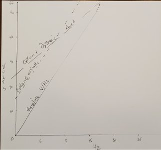
Looking at the graph 15Hz is my target speed, which for the 1800 rpm lathe motor is 450 RPM. After pushing this thru the back gear at 36:1 ratio I'd have a nice low spped of about 12.5 rpm, and a surface feet per minute of about 22 sfpm which is lower than rough grinding recommendation, to achieve the finish possible finish... at 12 rpm there is little kinetic energy and vibration that could transfer to the TPG.


1790108905464.jpeg


Now, examine the baseline V/Hz slope from 0 volts up to what is supposed to be 55 volts at the top. This is a nice simple linear curve. The issue is, this curve may not be enough for your motor's profile.

So we have the simple Option 0 boost potential. It merely raises the baseline linear expression by a voltage that we can never know unless we calculate it after observing the motor amps while the motor starts up. All we see is a Gain setting whcih the VFD then uses to look up a voltage in a table.

For the sake of this diagram I assumed that a gain setting resulted in a 15 volt addition. Notice the whole slope merely shifted up. When the motor hits 15Hz in this case it will be getting 15 volts more than necessary, that all goes into producing heat.

Finally, look at the line for boost Option 1. It's a dynamic boost calculated by the formula P72 x (P71 - real-time input voltage).

I used a few formula based on the graph data for the baseline, and Option 0 to calculate the factor that resulted in a 15 volt addition for the Option 0 offset.

Then I was able to use that to calculate the starting voltage for Option 1 based on the same setting input as parameter P72. That yielded the starting voltage of 25 volts and fixed the bottom of the slope in the graph. Trust me on the math, I dont want more typiing today.

NOW TO THE RELEVANT PART... look at the graph. This setting yields 66% more starting voltage, but quickly drops less than the voltage of the Option 0 boost by the time the VFD is supplying 7.5Hz, and then drops to zero added volts when the target 15 Hz has been met. This supplies only the voltage needed to maintain the speed. Option 0 continues to supply an over voltage condition until the VFD is stopped.

Now one person read this and say "Awesome" so I know I didn't waste my time.

Haha no need, this keeps the pixies in my head on alert and beats off dementia.
 
Back
Top