• Scam Alert. Members are reminded to NOT send money to buy anything. Don't buy things remote and have it shipped - go get it yourself, pay in person, and take your equipment with you. Scammers have burned people on this forum. Urgency, secrecy, excuses, selling for friend, newish members, FUD, are RED FLAGS. A video conference call is not adequate assurance. Face to face interactions are required. Please report suspicions to the forum admins. Stay Safe - anyone can get scammed.
  • The 2026 Calgary Area Meetup is set for Saturday May 30th at 10am. The signup thread is here! Robinhood has graciously offered to host the meetup again this year. Please note that you MUST RSVP to the notice linked above if you wish to come.

Working on my South Bend 9C

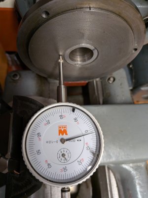
In post #575, the indicator tip was on the chuck body. What is the runout when on the back plate? I would check the outer edge just to the left of the chuck body, then check back side of the back plate, (only if it has been machined).
A 0.001+/- at the spindle shoulder runout will be larger farther away from the shoulder.
If there was a bit more material between the front of the shoulder and head stock, I would be tempted to take a very light facing cut off the shoulder.
There is a possibility that the collet chuck body was turned end for end when machining spindle mounting thread and then the taper and thread for collet and nut. Result, possible non parallel machining.
In picture post #500, were the bronze stock pieces with the lathe/spindle, as thought might have been to make bushings for the other spindle.

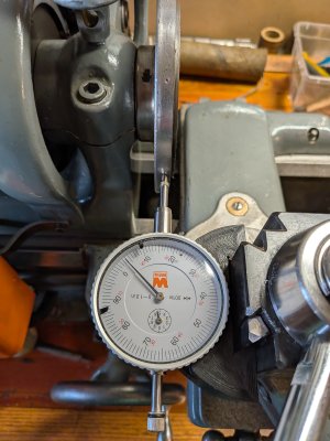
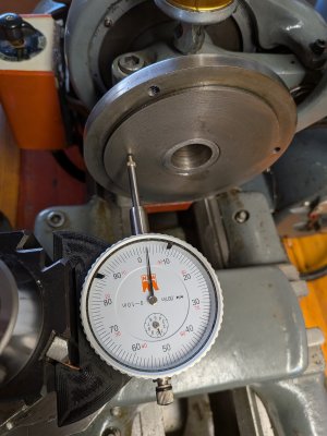
Chuck plate shows about 4 thou. Assuming those measurements are in the right places.
 

Attachments

  • PXL_20260108_224522426.jpg
    PXL_20260108_224522426.jpg
    1.6 MB · Views: 5
  • PXL_20260108_224849020.jpg
    PXL_20260108_224849020.jpg
    1.5 MB · Views: 4
You
Chuck plate shows about 4 thou. Assuming those measurements are in the right places.
Your second picture you're taking your reading in the righ place, but in the first one I don't think that is a machined surface, you want to be on that thin register machined into the backing plate...... I am still thinking you have a chip or burr on the spindle thread......
Was the high spot in the same orientation on the spindle with both chucks?
 
You

Your second picture you're taking your reading in the righ place, but in the first one I don't think that is a machined surface, you want to be on that thin register machined into the backing plate...... I am still thinking you have a chip or burr on the spindle thread......
Was the high spot in the same orientation on the spindle with both chucks?
Ope I'll try and get that second reading off the backplate this evening.

And yes, high point on both chucks was in line with the same spot on the spindle. (I will triple check again as well).

I'll check for burrs again but I've scraped that thing down with a pick and straight edges and brass brushes several times... (I would love to be wrong and have missed it)
 
Ope I'll try and get that second reading off the backplate this evening.

And yes, high point on both chucks was in line with the same spot on the spindle. (I will triple check again as well).

I'll check for burrs again but I've scraped that thing down with a pick and straight edges and brass brushes several times... (I would love to be wrong and have missed it)
It very well could present as a shiney spot on the side of the thread, they can get compressed on there so well that it's hard to tell it isn't really the parent material.
 
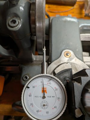
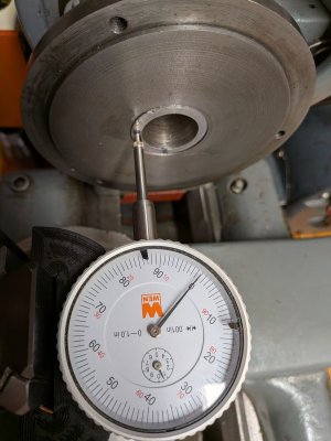
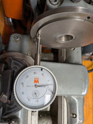
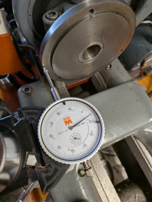
Couple more readings off the backplate for fun.

That register was hard to get at, so not sure it's a great reading, but about .002"

Then comparing against the nose of the spindle and a few points across the face of the plate, from 0 to .005" at the extremes.

Still not seeing anything pressed in there but this thing is so nicked and pock marked I could still just be missing it.
 

Attachments

  • PXL_20260109_031259829.jpg
    PXL_20260109_031259829.jpg
    1.3 MB · Views: 7
  • PXL_20260109_032342697.jpg
    PXL_20260109_032342697.jpg
    1.5 MB · Views: 6
  • PXL_20260109_032410997.jpg
    PXL_20260109_032410997.jpg
    1.4 MB · Views: 6
  • PXL_20260109_032437244.jpg
    PXL_20260109_032437244.jpg
    1.6 MB · Views: 7
Couple more readings off the backplate for fun.

That register was hard to get at, so not sure it's a great reading, but about .002"

Then comparing against the nose of the spindle and a few points across the face of the plate, from 0 to .005" at the extremes.

Still not seeing anything pressed in there but this thing is so nicked and pock marked I could still just be missing it.
Hi Michael,

In your first picture that is the register for the chuck, and if its been turned on that lathe should not show any runout or variation when you rotate the spindle by hand.

I deliberately turn the register on the backplate for the chuck about 10 thou too small, that way I can bump the chuck to reduce the overall run out or runout for a particular work diameter. For instance I get zero for work about 25 mm in diameter increasing as I go smaller or larger in work diameter.

In the second picture I would expect zero since that surface would have been machined on the lathe, and would stay at zero when the spindle is rotated.

The same would apply to the third and fourth pictures because that surface would have been machined on that lathe. Any wobble there would suggest that the backplate doesn't or hasn't been machined on that lathe.

HTH.
 
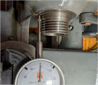
The measurements on the 2nd, 3rd and 4th image are not really relevant. Where you want to measure is where the chuck bolts to, which is the outer band. So in photo 4 move your indicator a bit farther out (away from the spindle) onto that face.
 
If the backplate will go on in a repeatable way (runout in the same pattern) there is no reason that you can't redo the chuck register. I realize this will not help the er32 issue but you could get the three jaw going.
 
The measurements on the 2nd, 3rd and 4th image are not really relevant. Where you want to measure is where the chuck bolts to, which is the outer band. So in photo 4 move your indicator a bit farther out (away from the spindle) onto that face.
Gotcha. That's about 6 thou.
 

Attachments

  • PXL_20260109_193253623.jpg
    PXL_20260109_193253623.jpg
    1.5 MB · Views: 2
If the backplate will go on in a repeatable way (runout in the same pattern) there is no reason that you can't redo the chuck register. I realize this will not help the er32 issue but you could get the three jaw going.
Yes I was thinking it could be a good learning opportunity!
 
Hi Michael,

In order to true the backplate for your lathe all you need to do is take a fine skim on the mating face for the chuck. if you now check on the side of the chuck (not the backplate) you will be able to measure the chuck runout. Putting a known round bar in the chuck jaws and checking that will tell you just how far the chuck is out.

As I mentioned before I turn the chuck register on the backplate slightly small so that I can true up the chuck by tapping it so that it moves and take out the runout, after tightening the chuck securing bolts to prevent any further movement the chuck should now run true.

Unfortunately this procedure will not help with your collet chuck. Based on other things that you have said it sounds like the collet threads are a bit loose or not quite in line.
 
I don't know these spindles well but isn't this the primary surface (being measured) what mates the screw on backplates/chucks back surface? For example if that has 0.001" TIR then an otherwise perfect 6" diameter accessory is going to show a magnified runout just based on larger diameter. Now if the chuck/plate mating face has its own (lets call it non perpendicular angle) runout then we get stacking complications. It will thread in until first contact, the high point of spindle & high point of chuck & you get what you get.

What does the book say about acceptable runout here?
Just eyeballing the spindle surface being measured looks like very small stick-out amount to the next diameter machined housing (ie. low clearance). Is that correct? I don't mean rubbing because you would surely hear that but is it maybe suggesting spindle has not been set sufficiently forward?

1767987891129.png
 
Hi Michael,

I made a new backplate for my ER32 100 mm diameter collet chuck. Actually the hard part was turning the internal threads in order to screw it onto my lathe spindle. I had a load of pictures of me making the backplate and fitting the chuck, I can't find them at the moment.

After I cut the threads I turned the backplate around and machined the other side flat and true. Then I machined the register for the new chuck. The secret here is that all the machining was done on the machine that the chuck was going to be used on. I have zero run out on the chuck body and tenths on the collets.
 
@PeterT From what I can tell, there is no appreciable run out at that measurement point. Jitters because it's not glassy smooth. A better indicator may help more. Not sure about the manual on that, I will see if I can find info.

From what I've seen, this generation of machines (mine is 1936) does have very very minimal stick-out of that spindle shoulder. Backing off the locking collar to allow it to move out would just introduce play, I don't see any way to control that distance..
 
Hi Michael,

I've found the pictures of making the collet backplate.

04-12-2024-001.jpg

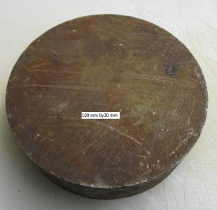
This is the piece of material that the backplate came from. It was a piece from the end of a bar found in a scrap bin.

04-12-2024-002.jpg

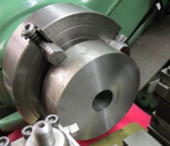
At this point it has been roughly centered in the four jaw chuck. Yo can see the lathe tool that I used to face the bar end off. Its also been drilled ready for boring to size for threading.

04-12-2024-004.jpg
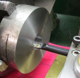
Here it is about to be bored to size for threading.

04-12-2024-006.jpg

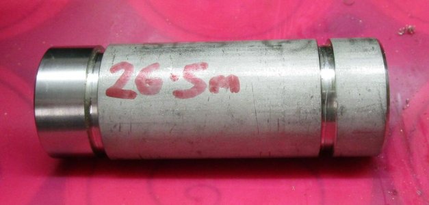
I made a plug gauge in order to get the right bore size for threading 1,1/8" X12 tpi.

04-12-2024-005.jpg

This is the bored backplate ready for threading. Ignore the saw cut in the side. That will get machined away later. The important bit is that the work has not been removed from, the four jaw and it was threaded right through. Guaranteeing that the thread is dead square to the face.

I've some more pictures but I've got to find them.
 
Back
Top