• Scam Alert. Members are reminded to NOT send money to buy anything. Don't buy things remote and have it shipped - go get it yourself, pay in person, and take your equipment with you. Scammers have burned people on this forum. Urgency, secrecy, excuses, selling for friend, newish members, FUD, are RED FLAGS. A video conference call is not adequate assurance. Face to face interactions are required. Please report suspicions to the forum admins. Stay Safe - anyone can get scammed.

Who can make sense of this?

Tinker

Member
Hello everyone, I'm new here.
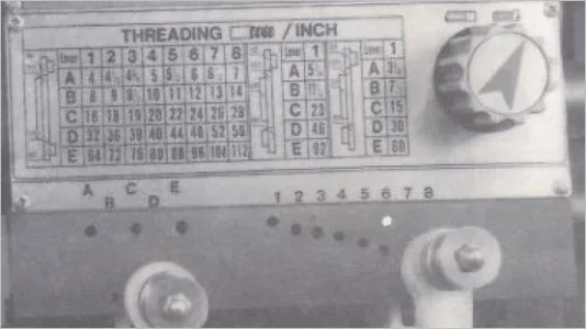
I really need help deciphering a 35 plus year old King 14x40 lathe's metric threading chart. I lost the manual a long time ago in a fire. It didn't help much anyways as it was a direct translation of the Taiwanese speak so it made little sense to me. So, I can make out the gears and their required position, but since I want to make a 1 mm thread pitch(per rev) on a shaft , where do I start?
Take a look at the picture. This is so odd.

20201212_094322.jpg

Any help will be greatly appreciated.
 

Janger

(John)
Administrator
Vendor
That is hard to decipher. maybe it's some sort of imperial representation of metric threads? How about reverse engineering it? cut threads with C4 and D4 and measure what it does?
 

Brent H

Ultra Member
That is a brutal chart - basically saying you can thread imperial threads by changing the gears to the pictured configuration and then moving the 40 tooth gear just gives you feeds that they list in metric? very strange - what is the threading on your lead screw? Is it metric or imperial
 

Johnwa

Ultra Member
Interesting chart! It has metric transposing gears which suggests a metric lead screw. But the gearbox seems to be imperial. With that combination I’m not sure a thread dial indicator would work. You would have to leave the half nuts engaged and run the lathe forward and reverse.

Anyway, the second set of numbers shows B2 will cut 0.98mm, which should be close enough.
The third set appears to be cross feeds.
 

PeterT

Ultra Member
Premium Member
Here is the equivalent chart on my King 14x40.
 

Attachments

  • SNAG-12-13-2020 0000.jpg
    SNAG-12-13-2020 0000.jpg
    163.9 KB · Views: 32

PeterT

Ultra Member
Premium Member
Its been a while since I looked at this. I know I have notes somewhere where I took inventory of the gears I have. But I think for 1mm pitch I can select
C-6 on 40-127-120-40 gears or C2 on 30-127-120-40 gears? This is with my IMP pitch lead screw of course, IMP lathe.
 

Attachments

  • 2020-12-13_9-35-21.jpg
    2020-12-13_9-35-21.jpg
    67.7 KB · Views: 23
  • SNAG-12-13-2020 0001.jpg
    SNAG-12-13-2020 0001.jpg
    29.3 KB · Views: 24

PeterT

Ultra Member
Premium Member
I was hoping to simply look at your corresponding gear/lever positions, multiply by 25.4 or something to come up with 1.0mm pitch, but the math is not cooperating. You may have a different gearbox layout than mine too, but I thought the gear ratios would work out to equivalent pitch. Do you happen to know the pitch of your threading leadscrew?
 

Brent H

Ultra Member
The gearing ratio's set up so that in Imperial threading the ratio is 1 : 1.058 and in Metric mode the Ratio is 1: 0.945 It basically would satisfy a lead screw that is imperial and divides into 24 - Like an 8 TPi lead screw 25.4/1.058 = 24 and 25.4 x 0.945 = 24 .. I would gather that the chart you supplied @PeterT in Figure 11 is correct for the lathe. I will check some math
 

Tinker

Member
Thanks for the help everyone. I told you guys it was odd. I will try C6 Peter's chart is showing. I'll also try and figure out if lead is metric or imperial.
 

Brent H

Ultra Member
@Tinker : There are a few issues with the whole set up - check out what your lead screw is. If it is 8 TPI and imperial there is a glitch, if it is a 3mm pitch lead screw - there is a glitch - but we have you covered:

If you have an 8 TPI lead screw you should have your gears set up like this for a 1 to 1 output for imperial threading:
C4EC8975-6D5E-4A9C-B1BF-3A3E72610E0F.jpeg
If you have a 3 mm pitch lead screw you will need to set up like this:

D4F9382F-915F-42CF-8E87-31069D04517D.jpeg

Looks like you have a pretty mutilated threading chart.

The math behind it basically works out like this: the gears in your selector box when put into C-6 gives you a 3:1 gear reduction. If your lead screw is 8 TPI and you are rolling out 24 TPI then 8 x 3 gives you the 24 TPI you require. If you are rolling metric out you have a gear reduction set up that provides a 1 to 0.945 ratio. 1 RPM x 8 TPI will yield a linear move of 0.118125" = 3.00 mm reduced by 3:1 gear reduction for a pitch cut of 1 mm.

If you have a 3 mm pitch lead screw the math is the same but opposite. Gear ratio of 1:1 on the drive gears x 3mm lead screw through a 3:1 gear reduction = 1 mm pitch. Reconfigure for Imperial or standard threading and you have a gear ratio of 1.058 So then (3 mm = 0.118125) x 1.058 ratio = 0.12498" (very close to the 0.125" of an 8 TPI lead screw) x the 3:1 ratio = 24 Threads per inch
 

Tinker

Member
Thanks to all who pitched in their 2 cents. Peter's chart works very well and is spot on. Yes after gauging the lead screw, it is 8 TPI. Brent your math is on the money and following your diagram confirms the butchery the Taiwanese made of the chart. I will print a new chart,etch it on a steel sheet and rivet the damn thing on it. Wow, you guys have no idea how frustrating this was for me. I'm so relieved and glad I found and joined this forum. Seems everyone is nice and no B.S. Thanks.............
 

RobinHood

Ultra Member
Premium Member
Something doesn’t add up just yet: the picture in post #1 shows that in order to get Imperial threads, the 120/127 inch/metric transposing (compound) gears need to be in play (green box). That suggests to me that the lathe has a Metric Lead Screw. If it had an Imperial Lead Screw, the path would be either straight through the 120T gear or the 127T gear alone (not through the compound).

3011128D-EF83-4083-A706-0239BBFD5E42.jpeg

@turner : if you are sure that you have an 8tpi imperial lead screw, then the chart in post #1 for SAE threads may not be correct (could just be that they drew the power path wrong?). At any rate (either with metric or imperial), in one system, the compound gear is in play and in the other it is not. There is no such thing as both systems using the compound gear.

Perhaps some trial threading is required to determine what is actually happening. Then adjust the charts accordingly.
 

Tinker

Member
OK, I'm convinced it's a 8 TPI Lead. Here some pictures albeit not the best. I need third hand. The 8 is from an Imperial (inch) thread gauge and if you noticed it's not sitting very square to the screw so looks a little off. But I can assure you it does fit much better then the 3.0 mm . The 3.0 if you look at it closely, the further left you go the more off it is.
Let me know what you think.
20201216_094516.jpg 20201216_094444.jpg
 

RobinHood

Ultra Member
Premium Member
Sure does look like 8tpi.

So that would mean that there is a problem with the thread diagram on your lathe. The compound gear (120T/127T) combo will not be required while threading in SAE (Green boxed item above). So now you need to find out if you need to run the 40-120-40 combo or the 40-127-40 one to give you the correct SAE threads (either one is 1:1 output, but only the one might physically fit with the shaft / gear location / space). Once you know, might be worth to redo that diagram as well to avoid any future confusion.

The compound gear IS required for Metric with an 8tpi lead screw - your new chart that you made would be correct.

Very nice chart, by the way!
 

Tinker

Member
Thanks RobinHood, Yes for sure I'll test and find out which gear set does what. Below and to the right of that chart just above the switching levers, there is also this chart. Just to add more confusion.
20201212_094006.jpg
 

Brent H

Ultra Member
@Tinker : That chart is correct for your lathe running imperial threading. The mistake on the original chart is that the title should have been :Metric Threading and the chart filled in with the metric pitches
 

PeterT

Ultra Member
Premium Member
The way I interpret my manual is:
If you have an 8 TPI leadscrew (or a 'screw leading stick' as some like to refer to it LOL) then only the upper chart red box applies
- the default 40>127>40 gears give you the TPI combinations on the left panel
- the 40>127*120>32 or 40>127*120>32 or 30>127*120>40 gear combos give you the metric threads on right panel
ps my symbol > means driving gear to gear and * means a face to face gear like their diagram

If you have a 3mm pitch leadscrew (a metric lathe typically) then only the lower chart applies
- the allowable mm pitches on the left & TPI on the right

Whatever leadscrew you have 8TPI or 3mm, disregard the other chart altogether. You cant achieve it because the leadscrew pitch is integrally in the driveline
 

Attachments

  • 2020-12-16_21-24-20.jpg
    2020-12-16_21-24-20.jpg
    184.4 KB · Views: 9
Last edited:
Top