
-
Scam Alert. Members are reminded to NOT send money to buy anything. Don't buy things remote and have it shipped - go get it yourself, pay in person, and take your equipment with you. Scammers have burned people on this forum. Urgency, secrecy, excuses, selling for friend, newish members, FUD, are RED FLAGS. A video conference call is not adequate assurance. Face to face interactions are required. Please report suspicions to the forum admins. Stay Safe - anyone can get scammed.
You are using an out of date browser. It may not display this or other websites correctly.
You should upgrade or use an alternative browser.
You should upgrade or use an alternative browser.
Tips/Techniques What are you printing today?
- Thread starter djberta
- Start date
Tips/Techniques

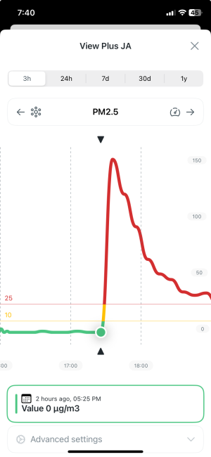
3D printer airborne pollution? Got any concerns? This shows the spike in PM2.5 coming off my machine for a print. I'm not sure how to assess this but I'm going to try to reduce it greatly as it seems to me like I'm breathing plastic.
My next project is to complete a filter system based on the IKEA UPPATVIND filters. There are downloadable prints for this.
My next project is to complete a filter system based on the IKEA UPPATVIND filters. There are downloadable prints for this.

TorontoBuilder
Sapientia et Doctrina Stabilitas
3D printer airborne pollution? Got any concerns? This shows the spike in PM2.5 coming off my machine for a print. I'm not sure how to assess this but I'm going to try to reduce it greatly as it seems to me like I'm breathing plastic.
My next project is to complete a filter system based on the IKEA UPPATVIND filters. There are downloadable prints for this.
FDM is just as great a concern as resin printers, and yes you get VOCs and ultrafine particulates, so small the penetrate deeply into the lungs.
Oh and they don't filter well using any desktop filter either. Exhaust fans are required for optimal health and safety. Or not, I'm in favour of Darwinism
Last edited:
Dan Dubeau
Ultra Member
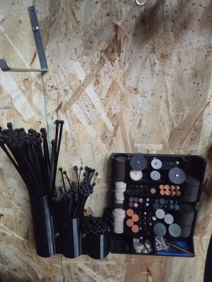
Well I'm going to try using the ikea UPPATVIND filter anyway and see what happens. Here is one half of the filter holder, the other half is on the printer. https://www.printables.com/model/1281236-ikea-uppatvind-core-one-hepa-filter-landscape/filesFDM is just as great a concern as resin printers, and yes you get VOCs and ultrafine particulates, so small the penetrate deeply into the lungs.
Oh and they don't filter well using any desktop filter either. Exhaust fans are required for optimal health and safety. Or not, I'm in favour of Darwinism

Doggggboy
Ultra Member
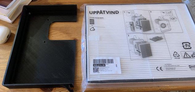
The best zip tie storage hack I've seen yet is to just cut a short slit, shorter than the zip ties, in the middle of the bag. Just reach in and grab one by the middle and it will pop right out. They can't fall out on their own because the slit is too short and with it being in the middle of the bag, the ends won't reach the slit even if you shake the bag.Quick and simple zip tie holder I designed and printed this morning. File below if anybody wants to print one too.
View attachment 89117

Dan Dubeau
Ultra Member
The best zip tie storage hack I've seen yet is to just cut a short slit, shorter than the zip ties, in the middle of the bag. Just reach in and grab one by the middle and it will pop right out. They can't fall out on their own because the slit is too short and with it being in the middle of the bag, the ends won't reach the slit even if you shake the bag.
Yup, that is the absolute best way I've found for keeping them in order on the job. I have a bag in my mobile box just like that. At home I don't want the bags though.
One of the reasons I bought ASA filament was so I could glue it to abs pipe and make a holder just like this (and other types of stuff) with various abs pipe scraps around. Only having to print the bottom.....Well, I never did get around to it, and got tired of not having one, so I just let er eat.
TorontoBuilder
Sapientia et Doctrina Stabilitas
Well I'm going to try using the ikea UPPATVIND filter anyway and see what happens. Here is one half of the filter holder, the other half is on the printer. https://www.printables.com/model/1281236-ikea-uppatvind-core-one-hepa-filter-landscape/files
View attachment 89185
It's all a matter of capture... trying to force all the particles thru the filter is like herding cats. Recirculating filtration is a difficult task to accomplish.
Printing chambers leak like sieves. Attachment points leak... spaces around the filters in the racks leak.
I'm sure you'll see a reduction in particulates, but little to no reduction in VOCs with the ikea uppatvind filter. Being a hepa filter that filter has a high static pressure drop and that could impact all your printer's default settings as the chamber heating and cooling ratees will be impacted, so that's something to look out for.
This is why industrial hygienists prefer to utilize local exhaust ventilation, such as a dedicated vent hood with engineered airflows and physical barriers to establish a negative pressure zone that captures and contains hazards directly at the source.
I'm not talking expensive or fancy here either, I'm building a hood from corroplast and an ecm motor bath fan from panasonic. Short walls projecting down to surround the printer on three sides for about 6 inches. That is enough to ensure pollutants are captured by the hood and exhausted.
Doggggboy
Ultra Member
Not a problem.Read that too fast and thought you printed zip ties for a minute.
Not that the holder isn't impressive but zip ties....

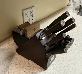
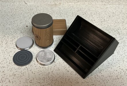

That is really cool.Bought a Horl to sharpen my knives and made a holder that goes in that lost space behind the knife block.
It has been posted on Printables.
Pierre
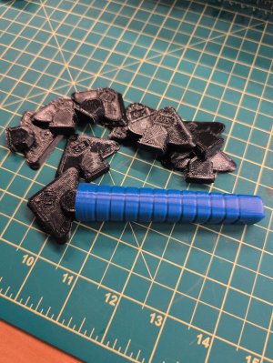
@TorontoBuilder any pics or even a sketch?I'm building a hood from corroplast and an ecm motor bath fan from panasonic. Short walls projecting down to surround the printer on three sides for about 6 inches. That is enough to ensure pollutants are captured by the hood and exhausted.
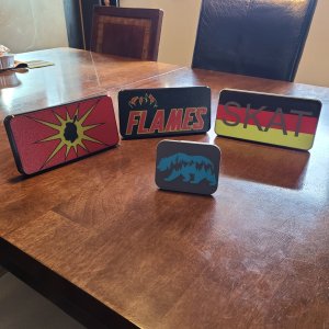

The filter made a dramatic improvement in PM1 and PM2.5 particles. I observed the following in my office. However...Well I'm going to try using the ikea UPPATVIND filter anyway and see what happens. Here is one half of the filter holder, the other half is on the printer. https://www.printables.com/model/1281236-ikea-uppatvind-core-one-hepa-filter-landscape/files
View attachment 89185
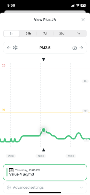
However, this article outlines additional concerns these simple filters do not cover as TorontoB was describing. I also have two open frame printers without an enclosure, a bambu A1 mini, and my old Prusa MK3+. What to do about those?
https://layercraftlog.com/fdm-printing/essentials-for-safety - highlight from the article
Enclosure Ventilation Standards
A passive enclosure does not equal safety. Per ANSI Z9.2-2018, local exhaust ventilation (LEV) for additive manufacturing must achieve ≥12 air changes per hour (ACH) with face velocity ≥0.5 m/s at the enclosure opening. For a typical 60 cm × 60 cm × 60 cm enclosure (216 L volume), this requires minimum airflow of 64.8 m³/h (≈17.9 L/s or 38 CFM).
Many users install 120 mm PC fans rated at ‘100 CFM’—but static pressure matters. At 10 Pa backpressure (typical for activated carbon + HEPA filters), most 120 mm fans deliver only 22–33 CFM (per manufacturer datasheets from Noctua NF-A12x25 and Delta AFB1212SH). Always size fans using the fan curve chart—not the free-air rating.
TorontoBuilder
Sapientia et Doctrina Stabilitas
@TorontoBuilder any pics or even a sketch?
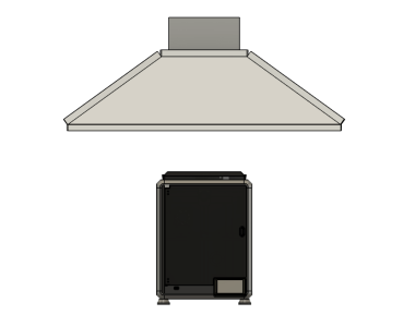
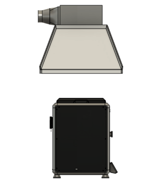
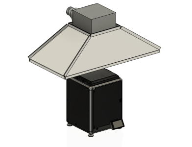
Here is an example of what I plan.
You can use cardboard, or like me coroplast with standing rib seams to fashion a simple exhaust hood with a square tray insert that a standard bath fan fits into via friction fit, or 3M foam tape.
A flex duct vents to the nearby window which is opened 6". A filler panel the same height as the window is installed in the 6" opening with a 4" exhaust port fitted into it. The panel I plan to use going to be 1" foam with aluminum fascia glued on each side, so I can leave it installed permanently and just need to plug to port when now in use.
Grommets in the four outside corners at the standing rib (not shown) are used to hang the hood. I have pulley style adjusting hangers from my hydroponic gear I will use to suspend my hood since I want the height adjustment so I can make the air capture zone smaller, by lowering the hood, when I use the really nasty solvents or fire the enameling / silver clay kiln for my wife.
I modeled this one 40" wide, which is good for two 3D printers.... but this size is going in our shop for the cold room with the heat treating oven. It will be sheet metal.
Front view.
Side View. 20" deep hood.
Isometric view
I ended up with a bunch of extra coroplast signs 4x4 feet - good material. @TorontoBuilder would your hood fan approach also work for open frame printers?
TorontoBuilder
Sapientia et Doctrina Stabilitas
@TorontoBuilder would your hood fan approach also work for open frame printers?
Of course this design will work with both open frame and enclosed printers... with certain caveats. This advice also applies ONLY to 3D printing risks. I'll address other risks and improvements after this section.
Several factors impact exhaust air capture, the airflow volume, airflow speed, and particle mass. Typically, higher mass requires higher velocity to move it. Because 3D printing particulates and VOCs are microscopic, our main concern is generating enough airflow speed to overcome background air movement in the room.
Our available air volumes are limited by standard residential exhaust fans, while our capture velocities depend on the open area between the hood and the work surface.
For the model shown the hood area is 40" x 20", which is 800 square inches, or 5.6 square feet in area. The average height above the work surface is 2 feet 8 inches for a total exhaust envelope of about 15 cubic feet in volume.
The ECM motor bath fan I plan to use has 3 speeds options and the ecm motor assures (within reason) that the full airflow is delivered with differing exhaust duct configurations.
On the low setting of 50 CFM the volume of air under the hood is turned over 3.33 times per minute. Looking at it another way the a air is completely replaced once every 18 seconds.
On the medium setting of 80 CFM the volume changes 5.33 times per minute, or is completely replaced once every 11.2 seconds.
On the high setting of 100 CFM the volume changes 6.67 times per minute, or is completely replaced once every 9 seconds.
Even at the lowest setting that is a very high ventilation rate enough to prevent fumes escaping the capture envelope below the exhaust hood.
BUT..
When an open canopy hood hangs above a source without side walls, air rushes in from all four open sides between the table and the hood rim. The volume of air exhausted is spread over this wide perimeter area, so the velocity is low.
In local exhaust ventilation design, the standard equation used to calculate the required airflow rate for a free hanging canopy hood is Q = 1.4 x P x D x V. This formula determines the volumetric airflow needed to capture rising contaminants across the open gap between the source and the overhead canopy.
Rearranged to solve for capture velocity v = cfm / (1.4 x P x D) where:
P = perimeter in feet which is the distance around all open edges of the hood.
D is the distance from the workbench to the bottom rim of the hood.
1.4 is a correction factor that accounts for uneven air distribution around the perimeter corners.
Therefore,
v = 50 / 1.4 x 10' x 2.68'
v = 50 / 37.52
v = 1.33 fpm
Not that high a velocity at all.
But the velocity increases as soon as the air passes the bottom plane of the hood opening, because the area decreases from an effective area of 37.52 sq. ft. (26.8 sq. ft. x 1.4 correction factor) to 5.6 square feet. At the bottom plane as air enters the hood the velocity calculation is simplified to a face velocitycalculation. V = cfm / area in square feet which in our case yields v = 50 / 5.6 = 8.9 fpm.
This still works for 3D printing because of thermal buoyancy. The heated print bed and hot end create a rising column of warm air. You don't need high suction at the table because heat naturally carries the particulates and VOCs upward into the hood's capture zone.
We aid this draft effect by lowering the hood so that the top of the printer breaks the bottom plane of the hood... and sit inside the hood space.
Once that warm plume crosses the bottom rim of the hood, the tapered walls squeeze the airflow from 5.6 square feet down to 1 square foot accelerating the air velocity from ~9 FPM at the plane up to 50 FPM at the fan opening so nothing stalls or spills back out.
Where the design hits its limits is with cold fumes and room temperature vapours, such as resin VOCs, isopropyl alcohol, adhesives, or solvent paints which lack that thermal lift. Without heat to carry them up the 32 inch gap, a cross draft can push them sideways before they ever reach the hood.
Even with a warm FDM printer, placing the setup near an HVAC supply register, open window, or busy walkway can shear the warm plume off center before it enters the hood. The same could apply if the printer uses high power parts cooling fans that blow air out of the capture envelope.
To make this hood handle room drafts, or open printers with high speed parts cooling fans, or non heated tasks, you have to shrink that open perimeter, either by lowering the hood closer to the source or by adding side and rear drop panels to block cross breezes and force all incoming air through a smaller front opening.
Closing off three sides converts the open canopy into a three sided booth, changing the formula to standard face velocity:
v = cfm / area
Instead of pulling air weakly from all four sides, the fan now draws air strictly through the single open front window. The sides and back block external air movement from affecting thee exhaust of contaminants, and keep parts cooling fans from pushing fumes out of the containment envelope.
v = 50 / ((40" x 32") / 144) = 50 / (1280 / 144) = 50 cfm / 8.88 sq ft = 5.63FPM
5.63 FPM across a full 32 inch high opening is fine for warm FDM printing with high speed part cooling fans, since the walls bounce the fan wash upward into the hood, but for cold fumes or heavy solvents, you should bump the fan to 100 CFM and add a partial front drop/sash, that will leave a shorter working window at the bottom. This would yield the following:
v = 100 / ((40" x 12") / 144) = 100 / (480 / 144) = 100 cfm / 3.33 sq ft = 30.03 FPM
Or since 40" is pretty wide an opening, you could use sliding door panels across the front, and access only a smaller area as needed. Say three panels 14" wide... making the widest possible opening about 14" which yields these calculation:
v = 50 / ((14" x 32") / 144) = 50 / (448 / 144) = 50 cfm / 3.11 sq ft = 16.07 FPM
v = 100 / ((14" x 32") / 144) = 100 / (448 / 144) = 100 cfm / 3.11 sq ft = 32.14 FPM