vertical lead in radius when plunging into a cut

Janger

(John)
Administrator
Vendor
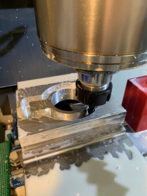
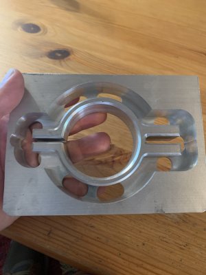
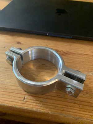
I'm milling out a the outside contour for a big bracket clamp. It is about 4" across. 0.05" plunge depth per trip around the outside of the part. The plunge is defaulted to be a ramp but with only a 0.04 radius. It goes THUNK into the cut. See the green preview in the simulation screen shot - the tool enters on the left sliding in and down from the very left. I'm thinking that I could change the radius to 0.25" and maybe it would be a lot smoother. I wonder if I'm damaging the EM doing this? Why does fusion default to 1/10 of the cutter diameter for the lead ins? wouldn't more generally be preferred? Oh and it's 15" per min and 5000 rpm. 12mm EM. Aluminium.


1689979019547.png 1689978949580.png


1689979213420.png
 

jcdammeyer

John
Premium Member
I saw a similar thing with the generated code for the pocket hole I was milling. Lots of options for ramping in.
I'm using the "Path" with those parameters.
I think it's important to look at the generated G-Code just like looking at the compiled assembler from C. Amazing how just a bit of rearranging can create quite different code.
1689986984807.png

1689986999606.png

1689987011184.png
 

Janger

(John)
Administrator
Vendor
Well I just let it run. The cutter seems fine despite all the thunks into the part. I have worn off the coating on the EM already.
 

Attachments

  • IMG_3964.jpeg
    IMG_3964.jpeg
    283.8 KB · Views: 9
  • IMG_3966.jpeg
    IMG_3966.jpeg
    322 KB · Views: 9
Last edited:

PeterT

Ultra Member
Premium Member
I'm more curious about what you're making unless its a Secret Squirrel project - an open gap slot on left side with a tightening bolt and a closed off gap on the right side.....also with a tightening bolt
 

jcdammeyer

John
Premium Member
Well I just let it run. The cutter seems fine despite all the thunks into the part. I have worn off the coating on the EM already.
This is a perfect example of why CAD/CAM and CNC can make things you can't easily do any other way. Although 3D printed pattern and lost wax along with boring the pipe clamp section perfectly round...

What did the raw billet for that cost?
 

Janger

(John)
Administrator
Vendor
I have a big hunk (3'x4' x 1") of aluminium left over from a water jet shop - it has a bunch of irregular shaped but salvageable sections. So it was not retail pricing on that material! I think the whole drop was $40. I wonder what metal mart would charge for that. plenty I'm sure. maybe I'll look. Well it's about 4 pounds of aluminium and last time I bought some it was $7 a pound. So it'd be at least $30 at metal super market, probably a lot more.
 

Janger

(John)
Administrator
Vendor
This is the drop plate I’m talking about. To use it I have to make multiple cuts with the jig saw and then the band saw.
IMG_3967.jpeg
 

Alexander

Ultra Member
Administrator
Definitely try plunging outside the part if you can. Seems possible here. But if your work holding gets in the way, go for a 2-degree ramp angle. Ramp down along the path, not radius down. It'll be easier on your end mill.
 

Janger

(John)
Administrator
Vendor
Definitely try plunging outside the part if you can. Seems possible here. But if your work holding gets in the way, go for a 2-degree ramp angle. Ramp down along the path, not radius down. It'll be easier on your end mill.
I didn't think of plunging outside the part. Thanks Alex that's good advice.
 

PeterT

Ultra Member
Premium Member
You might consider these curved standoffs or spacer washers (whatever they are called). A flat bolt on a curved tube is a tangent contact so not great for retention. On bike frames & similar accessories they are often brazed on permanent. But I've also seen them loose assembly like my Honda mower handles. If one is gronking the bolts to withstand trail rides, its better to have a solid or thicker core inside the tubing because its easy to deform in that squeeze orientation.

1690128053956.png 1690128085807.png
 
Top