Let me throw another monkey wrench into the works here.
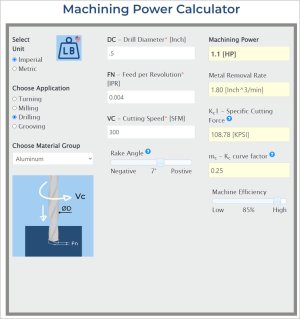
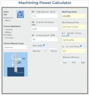
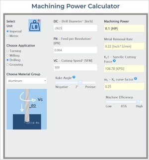
If he's got 1/2HP at 2500 and slows it 250 via VFD, he's got 1/20 of HP. I think you would agree you are not going to drill a 1/2 hole with 1/20 HP.
Likely not.
I believe the following are facts. Any argument with them? They are the extent of my point/claim
- HP = RPM x Torque
- Removal rate (cubic in inches/min say) is a function of HP
- VFD's don't increase torque over their range, when less than line frequency.
- The formula dictates, that if you don't increase torque as speed goes down, you get less HP.
You forgot one parameter that is critical in this discussion and applies also to other areas.
Torque = Amps x Turns.
- No one is drilling a 1/2 hole with 1/20 HP, which is about the power you could expect taking 1/2 HP @ 2500 and reducing it to 250 via VFD
As long as we buy the premise that with a VFD the current through the windings is not the same at 250 RPM as it is at 2500 RPM then your statement is valid!
What follows is another one of my long winded explanations.
One of the reasons the VFD manuals often say add external fan cooling to the motor if it runs for long periods at low speed under load is because in fact the VFD is designed, like stepper and servo motor drivers to limit the current at the motor specified current. And at low speeds the motor isn't turning fast enough to have the fan push enough air over the motor.
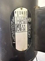
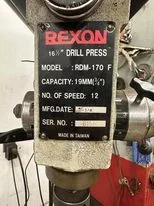
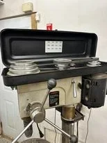
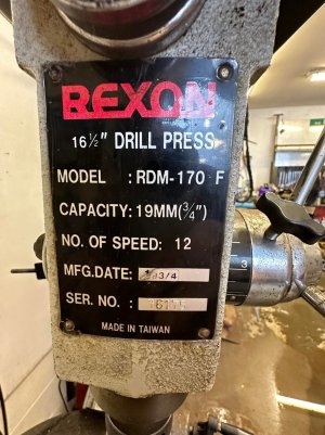
So. A motor like the one in the drill press has a 12A rating on it. Likely about 1.5HP with an 85% efficiency. So under full load at the standard 1725 RPM (I think that's the speed for 60Hz) 12A flows through the windings.
Now add the micro-processor to the mix along with a 1.5HP 3 phase motor. The VFD takes the 220VAC in, converts it to DC of about 310 VDC. The driver transistors to the 3 phase windings are energized with what is called Pulse Width Modulation to create three voltages that simulate 60 Hz signals that are 120 degrees out of phase relative to each other.
To do this they turn on the driver for a particular phase until the voltage reaches where it should be based on the sine wave it's trying to create. Say it's 100 slots in that 16.667 millisecond 60 hz wave. It won't turn on the driver for the full period in each slot: shorter at the lower part of the AC voltage; longer at the peak AC voltage. Perhaps fully on during the whole slot period at the peak voltage. So at 60 Hz and 1725 RPM at the peak of the AC wave form the voltage is also 310V. (I'll leave out the since that the current lags the voltage because we're dealing with an inductor since that will just confuse the point I'm trying to make).
The key thing is the pressure on the windings (voltage) at the peak of the AC waveform is 310 VDC which I get from 1.41414 x AC waveform and this forces the maximum 12A current into the windings.
OK. Let's change the frequency to 10 Hz which is generally the lowest output you'd get from a VFD. Again at the peak of the AC 3 phase waveform, the applied voltage will be 310 VDC. But likely a shorter time since the motor speed and the frequency is lower. We might still have 100 slots but the time the voltage is ON during those slots is shorter.
So why is that? Back to AMPs x Turns = Torque. Apply a voltage to a coil of wire and it takes a certain amount of time to start current flowing because of the inductance of the windings which itself is a result of the number of turns in the coil of wire.
And here's the key point! If the frequency is lower but the time to create 12A current in the winding remains the same then the time each driver in each phase slot is on is just shorter. But the 12A current can still be achieved.
So unlike a DC motor where all you do is reduce the voltage to slow it down, which results in less amps into the turns and therefore less torque, the AC PWM based VFDs try their very best to create a 10 Hz 3 phase waveform that matches the motor plate voltage and current.
And 12A at 10Hz is still the same torque as 12A at 60 Hz which is why HP is a value that just isn't that important.
One more thing. AC 3 phase motors will start to slip once the load is too high and the current is limited to the name plate voltage. That's why VFDs have a minimum frequency output. Lower than that and the motor doesn't work.
What makes AC servos work so well (they really are just 3 phase motors) is that the encoder on the back reports to the controller where the motor shaft is. So initially when tuning it, the waveform can be applied open loop without the encoder. That's how a STMBL AC servo drive kit is first run to make sure the correct phases are connected. Then the encoder is added to the feedback loop and now the AC waveform and current through the windings is tracked and more voltage is applied or reduced to maintain the correct position as the motor turns. I can turn my AC servo spindle motor on the mill at 1 RPM and there is no way I can stop it from turning by grabbing onto it.

