-
Scam Alert. Members are reminded to NOT send money to buy anything. Don't buy things remote and have it shipped - go get it yourself, pay in person, and take your equipment with you. Scammers have burned people on this forum. Urgency, secrecy, excuses, selling for friend, newish members, FUD, are RED FLAGS. A video conference call is not adequate assurance. Face to face interactions are required. Please report suspicions to the forum admins. Stay Safe - anyone can get scammed.
-
Several Regions have held meetups already, but others are being planned or are evaluating the interest. The Calgary Area Meetup is set for Saturday July 12th at 10am. The signup thread is here! Arbutus has also explored interest in a Fraser Valley meetup but it seems members either missed his thread or had other plans. Let him know if you are interested in a meetup later in the year by posting here! Slowpoke is trying to pull together an Ottawa area meetup later this summer. No date has been selected yet, so let him know if you are interested here! We are not aware of any other meetups being planned this year. If you are interested in doing something in your area, let everyone know and make it happen! Meetups are a great way to make new machining friends and get hands on help in your area. Don’t be shy, sign up and come, or plan your own meetup!
You are using an out of date browser. It may not display this or other websites correctly.
You should upgrade or use an alternative browser.
You should upgrade or use an alternative browser.
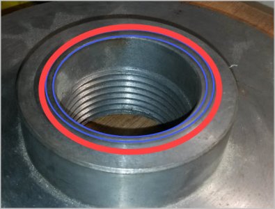
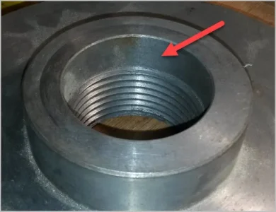
Turning the thread on a chuck mounting plate
- Thread starter SparWeb
- Start date
@YYCHM other than making sure it’s centered yes. The compound moves the tool longitudinall. If it’s set at30 deg. It also moves it in or out. The crossslide just does in and out.
What do you mean by centered? I'm puzzled about re-entering the thread.
Absolutely the right way to go. it does take a little calculation, which is provided with the thread mic, but is way better than using thread wires. I have yet to find a place where it isn't.Then I got a thread mic a few years ago. I would never go back.
Nope.... that doesn't make any sense to meAre you saying I can mount that backplate any which way and still hit the start of the thread every time?
Notwithstanding the missing entry point, the idea is to setup as though you were gunna thread, engage the half nut, and then move the compound and cross-slide to make the threading tool fit into the existing thread where ever it is. I usually do that with the part turning to take up the back lash. Sometimes you have to take multiple shots at it.
The point I was trying to make about the 29.5 degree difference VS 30 degree is that the purpose of the 29.5 is to keep the thread surface clean with a nice flat face on the threads. When you do that, I slowly eats away at the initial entry point. So it isn't there anymore when you reach full depth. Therefore you cannot clean up or repair a big thread as easily as you can a small one.
I think it might be possible though if you set the tool at full depth, then back out, and then ignore the fact that it doesn't look right when it is following the existing threads. I believe it will work out in the end.
I'd be happy to test this tomorrow to make sure.
I think it might be possible though if you set the tool at full depth, then back out, and then ignore the fact that it doesn't look right when it is following the existing threads. I believe it will work out in the end.
I'd be happy to test this tomorrow to make sure.
Darn terminology again. I used the word 'chasing' which is probably wrong for this discussion. You hear about people chasing a thread with the same size tap for example. This implies 1) the helical tracking is the same 2) the thread DOC is the same.
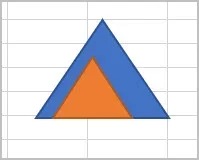
LH cartoon. If the existing thread (orange) is smaller for whatever reason (shallow DOC, even incorrect section) but the correct thread (blue) can envelope that section because its larger, then there is a small degree of latitude on the tracking or phasing. The theoretical crest points do not have to perfectly line up.
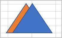
RH pic. If the section is already to depth, then you must phase the thread exactly or it will result in a wider section cut.
LH cartoon. If the existing thread (orange) is smaller for whatever reason (shallow DOC, even incorrect section) but the correct thread (blue) can envelope that section because its larger, then there is a small degree of latitude on the tracking or phasing. The theoretical crest points do not have to perfectly line up.
RH pic. If the section is already to depth, then you must phase the thread exactly or it will result in a wider section cut.
Attachments
A more commonly accepted term is thread 'Class'. When you specify the OD, Pitch & Class, the calculations spit out the allowable min/max range of the entire thread form for both internal & internal threads. The most defining term is pitch diameter (PD). Attached PD table for OP's 2.25 x 8 TPI. A lower Class# is equivalent to a larger PD difference between male/female, another way of saying looser tolerance. A higher class # is equivalent to smaller PD difference, tighter or more precision tolerance.
Not sure if this is more of a visual aid but the story goes: temporarily forget the threads & picture a shaft & hole. The male shaft has it's diameter & hole has its diameter. Lets pretend those are named pitch diameters. A larger PD gap between the two is equivalent to a wider allowable range of displacement (tolerance) & vice-versa. When you superimpose a thread form on these surfaces, similar displacement can occur (within the limits of premature interference from the crest/trough/radii thread form which is maybe where the analog story gets weak).
UN imperial screw thread calculator
theoreticalmachinist.com
Not quite sure why you are telling ME this Peter. If you read my post that you quoted, you will see that I referenced thread classes there because I know that the fit class matters - especially for interchangeable parts.
What I was trying to explain/understand is why @Johnwa & @YYCHM are so insistent on a tight perfect fit.
The registration is of course necessary, but I don't see why a tighter fit on the thread is necessary in this case. In fact, I can see several reasons why it might not be a good idea. It might prevent the registration from doing its job, and it might also lead to galling.
Getting back to my original question here..... How does one setup to have the tool re-enter the thread accurately?
Watch the Joe Pi video.
Just pretend you have a smaller thread and forget about my 29.5 VS 30 degree concern for now.
Getting back to my original question here..... How does one setup to have the tool re-enter the thread accurately?
And if the Joe Pi video doesn't work for you, I'll happily walk you through the process one step at a time.
And keep in mind that Joe is talking about repairing/completing an existing thread. You are taking about adding more length to an existing thread. Those are two different things.
And if the Joe Pi video doesn't work for you, I'll happily walk you through the process one step at a time.
And keep in mind that Joe is talking about repairing/completing an existing thread. You are taking about adding more length to an existing thread. Those are two different things.
I'm not looking to have anything done. The OP want's a partially threaded backplate finished....
I'm not looking to have anything done. The OP want's a partially threaded backplate finished.... Maybe you should read the whole thread?
Yes, I saw that. But I assumed (probably incorrectly) that you were doing the same thing.
So what are you doing that causes you to ask how to pick up a thread?
Yes, I saw that. But I assumed (probably incorrectly) that you were doing the same thing.
So what are you doing?
Nothing LOL.... My lathe is too small to help this guy out AND I've never internally threaded before. Was just pondering on how to set that situation up..
Nothing LOL.... My lathe is too small to help this guy out AND I've never internally threaded before. Was just pondering on how to set that situation up..
I see...... LOL!
Ya, watch the Joe Pi video.
It's a skill you will appreciate having in your tool box when/if you ever need it. It really isn't that hard to do once you know how.
How does that saying go? Something like: "This problem too will be simple when solved." ...... LOL!
@Susquatch the thread fit and shoulder registration is very important if you’re using a screw on collet chuck. That’s what I’ve been fighting with. Another case is if you need to take the chuck on and off for some reason (like checking for fit on the spindle). The threads act as a very steep taper and can’t be relied on to center the chuck. That’s where the shoulder registration can help. As @YYCHM and I have found, the off the shelf backplates have lots variation (>0.005”) in the registration bore so not a lot of help. I have one 3jaw that does register properly on my lathe. I use it as a standard but haven’t been terribly successful duplicating that fit.
I agree that the registration is important. Could it be that your attempt to make a perfect fitting thread is interfering with the ability of the backplate move around enough to center on the registration?
Darn terminology again. I used the word 'chasing' which is probably wrong for this discussion. You hear about people chasing a thread with the same size tap for example. This implies 1) the helical tracking is the same 2) the thread DOC is the same.
LH cartoon. If the existing thread (orange) is smaller for whatever reason (shallow DOC, even incorrect section) but the correct thread (blue) can envelope that section because its larger, then there is a small degree of latitude on the tracking or phasing. The theoretical crest points do not have to perfectly line up.
RH pic. If the section is already to depth, then you must phase the thread exactly or it will result in a wider section cut.
I don't think I know anybody who can whip together drawings as fast as you can.
You have a genuine talent for it and I am jealous!
SparWeb
Active Member
Thank you for the Joe Pie video link. That's a novel approach using the dial indicator that I wouldn't have thought of. The size of ID thread and pitch is close to what I have to work with here.
A little bit of investigation on my part has turned up an explanation for what happened to this backing plate. I found in a box of odds and ends a custom-cut tool steel threading tool. It perfectly fits into the groove of the thread, but it's not deep enough to complete the cut! If that's what the fellow did wrong, I don't know why he didn't just grind the "neck" down a little more to get more clearance but it's already pretty mangled as it is.
Regardless of how it got this way, your ideas and suggestions are making it seem more likely that I can fix this guy myself. And if I screw up, I can just get another backing plate and be done with it.
I'll get back to the threading tangent when I have some more time because I think there is still some remaining miscommunication there.
But I want to circle back to your spindle. Do you have a manual or specs that clearly defines presence of & dimensions of a register surface? From what little I've seen of threaded spindles, they vary, but I'd be surprised if a register was not present & a critical part of the fit-up. And has the register surface already been machined on the backplate or that is still untouched?
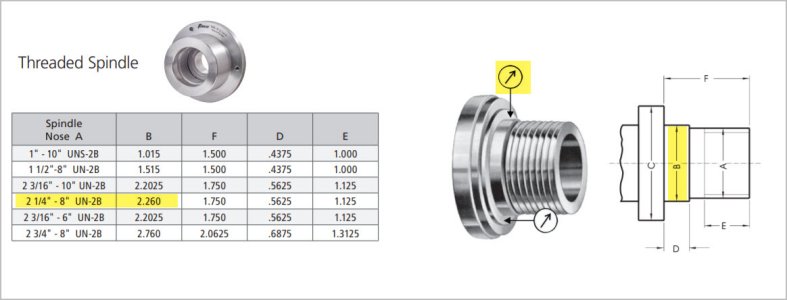
The 2.250 x 8 TPI example pic I found shows the register OD as 2.260" (no tolerance provided). Works out to .010" over the nominal external threaded major diameter, but that's probably just peripheral info related to manufacturing. If we guessed at 0.001" diametric clearance, you would have to machine the backplate register recess to 2.261" ID. But better yet, measure your lathe to confirm & try & get a handle on what the register recess dimensions should be. Ideally the threads & register would be done in same setting. So looser class threads may not directly impact fit, because the plate mates the register. But maybe there is some other parameter I'm not aware of like looser threads more prone to backing off or something? I dunno. Would feel better working off a spec vs guessing.
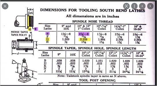
I don't know much about Southbend's, but example pic shows 2.250 x 8 TPI spindle, 2.259" register OD, so 0.009" over external thread diameter. Length (H-F) is 0.250" So kind of similar
Not sure I understood YYCHM comment that the area behind the thread (the register?) didn't matter, unless a different nose again? Maybe he can clarify. I could see if a threaded spindle integrated a tapered nose, plate would self center on that.
But I want to circle back to your spindle. Do you have a manual or specs that clearly defines presence of & dimensions of a register surface? From what little I've seen of threaded spindles, they vary, but I'd be surprised if a register was not present & a critical part of the fit-up. And has the register surface already been machined on the backplate or that is still untouched?
The 2.250 x 8 TPI example pic I found shows the register OD as 2.260" (no tolerance provided). Works out to .010" over the nominal external threaded major diameter, but that's probably just peripheral info related to manufacturing. If we guessed at 0.001" diametric clearance, you would have to machine the backplate register recess to 2.261" ID. But better yet, measure your lathe to confirm & try & get a handle on what the register recess dimensions should be. Ideally the threads & register would be done in same setting. So looser class threads may not directly impact fit, because the plate mates the register. But maybe there is some other parameter I'm not aware of like looser threads more prone to backing off or something? I dunno. Would feel better working off a spec vs guessing.
I don't know much about Southbend's, but example pic shows 2.250 x 8 TPI spindle, 2.259" register OD, so 0.009" over external thread diameter. Length (H-F) is 0.250" So kind of similar
Not sure I understood YYCHM comment that the area behind the thread (the register?) didn't matter, unless a different nose again? Maybe he can clarify. I could see if a threaded spindle integrated a tapered nose, plate would self center on that.
Attachments
Last edited:
As [USER=993]@YYCHM and I have found, the off the shelf backplates have lots variation (>0.005”) in the registration bore so not a lot of help. I have one 3jaw that does register properly on my lathe. I use it as a standard but haven’t been terribly successful duplicating that fit.
Ah, think I get it. The machined register & thread diameters are non-concentric?
What if you machined a steel ring, ID is perfect desired fit on spindle register diameter. The ring OD is whatever, lets call it 2.750". Rough turned OD finish is better. Now you counterbore the backplate larger ID yet, say 2.800" so it can accommodate non-concentricity. Put the ring on spindle register. Wait back up - put some releasing agent on the spindle! LOL Smear small amount of Loctite retainer or epoxy inside the counterbore ledge so it will tack the front edge of ring. Screw the backplate on. Threads center how they may. The ring gets tack set in plate overbore recess, but now concentric with threads. Unscrew assembly, ring stays stuck in position in plate. Back fill resulting (offset) annular gap with JB-Weld. Hard to annotate, hopefully makes sense.