I'm slowly figuring out weldments in my CAD program. More for fun but also to have that knowledge. I was going to download or internally generate some section profiles which can then be used to rapidly build structural assemblies based on relatively simple 3D line drawings.
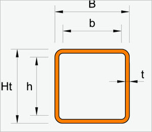
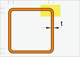
Anyways, I noticed that the tubing corner radius is not readily provided on rectangular sections. I can understand that it may well vary, but find it kind of odd its not part of the typical table for a specific supplier or some defined standard. I called Federal Metals to inquire about price & also ask if they sold a certain brand so I could look up a corresponding catalog or mill name, but didn't quite get a definative answer. They said the corner varies by supplier even on same nominal size
https://www.cad-steel.com/steel-sections/hss-shapes-rectangular-and-square
How do you welders work around this? Is there a spec or parameter I am missing or do you just adjust the fabrication based on what is sold?
Have any of you Fusion guys downloaded structural tubing design libraries libraries like this, or are they internal stored maybe?
Sidenote, one can access all the profiles, bracketry & fittings for 80/20. But you have to rob a bank to buy the stuff! lol
https://8020.net/tools-cad
")