• Scam Alert. Members are reminded to NOT send money to buy anything. Don't buy things remote and have it shipped - go get it yourself, pay in person, and take your equipment with you. Scammers have burned people on this forum. Urgency, secrecy, excuses, selling for friend, newish members, FUD, are RED FLAGS. A video conference call is not adequate assurance. Face to face interactions are required. Please report suspicions to the forum admins. Stay Safe - anyone can get scammed.

Tool Tools to set angle on compound fairly accurately?

Tool

StevSmar

(Steven)
Premium Member
I watched a Joe Pi video recently where he uses a bit of trigonometry to set the compound ultra accurately.

If it only needed to be within say 1/2 a degree, what would a good tool be to do this?

I needed to cut an 82 degree taper for a countersinking tool and the dial on my lathe didn’t go that far, so I had to resort to using a woodworking bevel gauge.

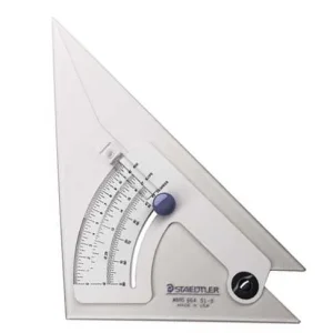
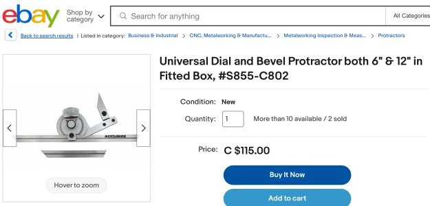
Would this tool work:IMG_9393.jpeg
 
Would this tool work:

I have two. They are not that good. The two edges are not aligned. I chatted with @Dabbler about ways to fix it and then we forgot when he was here.

I think it would be ok to a half degree provided it is perfectly made and calibrated. Lotta ifs & I have no faith that another would be better.

Also, I tried making a taper using a rotating angle gauge. NFG. An indicator and trig is the only way to go. Flawless method.
 
There was a good discussion about that in this thread.

 
like susquatch said , an indicator is going to get you pretty close. I had a steep learning curve to go through when I had to cut/grind a B&S taper for my grinder. I used two indicators to get the proper rise/run set for the lathe compound, cut the taper and then used the universal grinder to finish. Did a real good job of getting the right taper that way. If its just for countersinking a screw your lathe should do a good job with indicators.
 
There was a good discussion about that in this thread.

Ya, I still have not finished that project......... Need to put that back on the front burner........

But keep in mind that this was never intended to be more accurate than a half degree or so for quick angles like threading. I doubt it would be accurate enough for tapers. On the other hand, if I can add a Vernier scale to it, maybe it would.
 
Last edited:
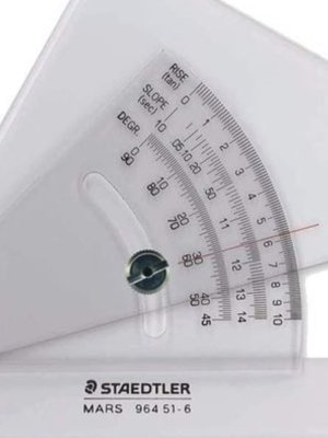
I use one of these.

At least on the surface, that looks like it might be better than the subject of this thread. I believe it was designed to be used for drafting, but who is watching.

By the way, the newest one of yours doesn't look like half what you have....

Screenshot_20240511_193840_Pinterest.jpg
 
Last edited:
Mattys workshop has a lathe sine bar and how to use it.
I made a version of this but haven't used it yet as I'm lacking gauge blocks.
 
The one Bob Ward presents here is the best idea I've seen.


Of course you don't need gauge blocks and sine bars for 1/2 a degree (aren't the degree graduation marks good enough for that?) but thought i'd include it in the discourse on the topic, for posterity :)
 
Of course you don't need gauge blocks and sine bars for 1/2 a degree (aren't the degree graduation marks good enough for that?) but thought i'd include it in the discourse on the topic, for posterity :)

Agreed completely - even a quarter degree can be good enough with a careful eye and a scale with an accurate index.

The problem is those poor souls like me who have compounds that only have scales for +/- 30 degrees instead of all the way around 360.
 
Well, 82° is the included angle, so you only have to set our compound to 41°.
I was being cheap. The brass I was turning was maybe 4” long, so I couldn’t set my compound the normal way without it hitting the chuck, so I needed to rotate it around by 180 degrees from my lathes 41 degree mark.

Now I realized I missed a good opportunity to purchase more stock…
 
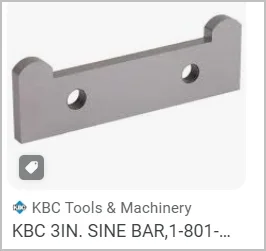
My method is straightforward, but I think pretty accurate. I can take some pics but maybe description will suffice. You need some kind of accurate reference bar to be held in the chuck (or inserted into MT socket if you go that route). And you need a sine bar. I prefer this thinner plate style like pic because I can mount it in my toolholder gap.
- chuck the reference bar, rotate & ensure its concentric to lathe spindle axis (no runout on inboard vs outboard end)
- mount DTI on the compound & feed compound along bar so its indicating zero (ie compound is traversing exactly parallel to bar, call this initial zero degrees)
- insert sine bar plate into toolholder gap, lightly tighten set screws, ensure both lobes are touching bar, secure in this position. Now the sine bar is registered zero to the test bar
- now loosen compound so it can rotate. Insert the appropriate spacer block under one sine bar lobe, the other lobe is contacting the bar (standard angle setup methodology). This sets compound to the desired angle within the tolerances of aforementioned setup.
- The End

This method works best with shallow angles (say sub 25-deg) relative to reference because its limited by the spacer block size before getting unwieldly. If you wanted to offset an angle relative to the face plate, its the same procedure just using face plate as initial zero reference.

1715970280473.webp1715969326922.webp
 
It started raining here today so planting is on hold.

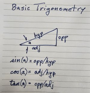
I'm not really a fan of actual sine bars when setting compound angles. I like to take the arc-tangent of the resulting compound displacement divided by its associated horizontal carriage displacement. The result is the compound angle. Its really as simple as that.

Here is the Basic Trigonometry.
20240517_183439.jpg

Note that using these definitions, the lengths don't need to be unitized. They can be anything.

Here is an example setup.
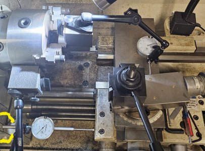
20240517_173022.jpg

This photo is not really what I do, but it will serve as a better example photo than what I really do. Fundamentally, I don't like long indicator holder arms because they bend. So my actual process has the compound right under the chuck and both indicators are attached to the chuck. Note that some of this long arm bending is negated by locating the rear of the horizontal indicator so that it touches my gear box. (Outlined in yellow on the photo.) But the compound indicator is on a long arm suspended in the air - which basically sucks.

It is VERY IMPORTANT that the two indicators be set perpendicular to the two axis of the lathe so that they measure the actual desired displacement.

Note that the angle set on my compound is 7 degrees or as close to that as my eyes will allow.
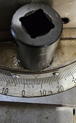
20240517_174320.jpg

Both indicators are zeroed. Then the cross-slide is moved by whatever amount you want and then readings are taken on both indicators. It is not necessary to move certain discrete amounts like 1" or 2". However, the longer the distances, the better the resolution of the result.

In this case, the compound displacement was 0.124 and the cross-slide movement was 1.000. It isn't necessary that it be 1.000 it just makes the division math easier.

Opp/Adj is 0.124/1.000 = 0.124

ArcTan of 0.124 = 7.068 deg.

It also doesn't matter if your indicators are metric or imperial as long as they are both the same.

It's actually easier to measure an angle this way than it is to set it to a specific angle. But either way, it's WAAAY more accurate than using angle gauges and such.

If your lathe and indicator setups are such that hysteresis of the readings cannot be avoided, then I suggest that several readings be taken in each direction and the results averaged.

Don't assume that one reading nails it. It is important to be aware of hysteresis. On this particular setup, I found that repeating the long axis in both directions resulted in about 2 thou change in the compound reading depending on which way the two indicator plungers were moving (in or out). That 2 thou changed the angle to 7.18 degrees from 7.07. So in this case, I would average those two angles to 7.12 degrees. This difference is the reason that I like short rigid indicator arms. You can never get zero difference but it's nice to get close.

In this setup, the difference was half the first one. Which makes sense because only one arm is bending and the other is straight.
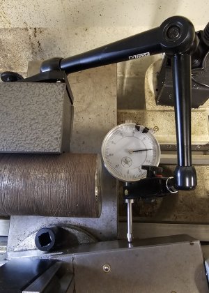
20240517_192420.jpg

As always, setting up something like this as a demo, spawns ideas. I have a carriage stop indicator planned which would eliminate arm flexing for the carriage measurement, but I should make something short and rigid to mount the compound indicator on. That would eliminate arm flex for both indicator holders leaving only the internal hysteresis of the indicators themselves to deal with.
 
I’ve only ever done the indicator method like @Susquatch has outlined above. It’s not too difficult once you get to doing it. The math is important, but it’s a foolproof method other then the simple calculation.

It got me an excellent fitting taper for my mill fine down feed mechanism…..
 
To set the compound to a specific angle, one good method is to measure the length of your compound. Use that length as the hypotenuse and then calculate the length of the opposite side (multiply by the sine of the desired angle). Make a spacer that long and adjust the compound so that one corner touches the stock and the other fits the spacer.

If the compound it too low, or you want more accuracy, make a bar that fits in the slot for the tool post and extends longer. In general, the longer the better

It does assume that the cross slide actually moves parallel to its body, but the only way to find that out is to actually cut a taper and then measure it
 
It does assume that the cross slide actually moves parallel to its body, but the only way to find that out is to actually cut a taper and then measure it

Excellent point. I remember checking mine when I first got my lathe. It's a fundamental requirement.

But I think most lathes are pretty good in this respect.

Wouldn't work on a compound with beautiful curves.
 
I think that the outside of the compound and the wedge slot are intended to be very parallel. But a worn slot or incorrectly adjusted gib can throw that off.

It also depends on the type of gib. Whether it is a tapered wedge shape adjusted for tension with a single screw at the end, or a flat wedge shape adjusted with 2 screws from the side.
 
Back
Top