• Scam Alert. Members are reminded to NOT send money to buy anything. Don't buy things remote and have it shipped - go get it yourself, pay in person, and take your equipment with you. Scammers have burned people on this forum. Urgency, secrecy, excuses, selling for friend, newish members, FUD, are RED FLAGS. A video conference call is not adequate assurance. Face to face interactions are required. Please report suspicions to the forum admins. Stay Safe - anyone can get scammed.

Today's project

ShawnR

Ultra Member
Premium Member
I have one of these (similar to) on my electronics bench

https://www.globalindustrial.ca/p/o...dYwdXBl8BK30e4nHfuQcqmZtV2tn7ShhoCgjMQAvD_BwE

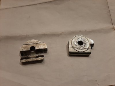
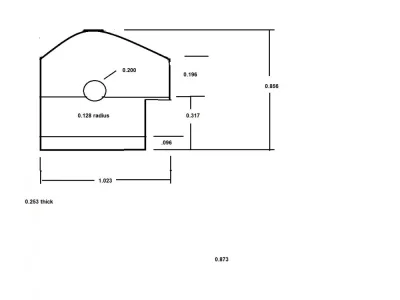
Where the light assembly attaches to the upper arm, there is a split bushing/friction lock/insert that is probably cast aluminum and has broke. I glued it back together to take measurements but looks like it will be the project de jour

Roughly 1 inch wide by 7/8" tall by 1/4" thick (each part)
 

Attachments

  • 20210205_061207.jpg
    20210205_061207.jpg
    74 KB · Views: 25

CalgaryPT

Ultra Member
Vendor
Premium Member
That will keep you busy. I have a similar mag lamp, also on my electronics test bench. I keep meaning to replace it with an LED model, but I have two replacment round fluorescents for it, still unboxed. So unless I find a great deal, it's old school for me for a while longer.
 

ShawnR

Ultra Member
Premium Member
I should have started on it when I went to the shop this morning,..but got sidetracked. So today's project might become tomorrow's...
 

ShawnR

Ultra Member
Premium Member
Almost done. But close enough for posting purposes. Looks like they will work. I am not sure about "texturing" for locking the lamp in various positions but I figure if it needs something, I might put a knurl on it or insert rubber gasket/washer/disc. A bit of fit and trial to do tomorrow. Honestly, no need for a mill on this one. I roughed them out on the bandsaw, milled to the traced scribed line (mostly cause I wanted an excuse to use the mill), then finished with a file and sanding disc. Having said that, The mill, being used as a rigid accurate drill press, was good for drilling the hole (concave feature which is a pivot point). I never took a picture but I clamped the two old pieces together, (after gluing them back together to get better dimensions) determined that a 5/16" bit would cut both halves nicely if bolted together, then did as much of it as I could with a 5/16 2 flute end mill. When I ran out of cutter length, I finished with a 5/16 drill bit but at least I had a good guide by then.

I am hoping the brass stands up better than the aluminum as I only got about 8 years out of that.....:rolleyes: ;)

As an aside, I see the CAD thread running. I have wanted to learn CAD for years and started many times but usually/always gave up. Working from drawings like that is really nice to do, but for the stuff I do, a napkin is more efficient. Lately though, I have been sketching stuff up in Paint, even if just to the point where I can write the dimensions on later or in the shop. I find the dimension lines are a pita to do sometimes. The drawing can be fun. So I threw that pic in here as well. Someday, I hope to concentrate on learning a CAD program. I will follow that thread.

Happy Superbowl day! (Not a huge football follower but I like the food associated with the game....)

Cheers,
Shawn
 

Attachments

  • Step 1ish.jpg
    Step 1ish.jpg
    156.3 KB · Views: 21
  • Step 2ish.jpg
    Step 2ish.jpg
    140 KB · Views: 23
  • Finished parts.jpg
    Finished parts.jpg
    74.4 KB · Views: 20
  • Bench lamp drawing.jpg
    Bench lamp drawing.jpg
    29 KB · Views: 19
Top