• Spring 2024 meetup in Calgary - date Saturday, April 20/2024. discussion Please RSVP Here to confirm and get your invitation and the location details. RSVP NOW so organizers can plan to get sufficient food etc. One week to go! More info and agenda
  • We are having email/registration problems again. Diagnosis is underway. New users sorry if you are having trouble getting registered. We are exploring different options to get registered. Contact the forum via another member or on facebook if you're stuck. Update -> we think it is fixed. Let us know if not.
  • Spring meet up in Ontario, April 6/2024. NEW LOCATION See Post #31 Discussion AND THE NEW LOCATION

Tig vs power panel

JohnW

(John)
Both conduits have easily removable covers on the LB's. Take them off and see what is inside.

Turn off all the breakers in your garage panel and see if you still have power / lights anywhere possibly fed by the second conduit.

Take the cover off your house panel and see what is connected to the two sets of 40A breakers. they should be thick (i.e. 6-8 AWG wires), vs the usual thin (14 AWG) wires connected to 15A breakers. Can you see where the wires from the house panel go?
 

Dabbler

ersatz engineer
So peter, this is why having a look might be helpful. It might find a problem (heaven forbid) or it might help to explain why it so confusing. I was trying to avoid long explanations, especially with conditional statements (if 'this' then 'that'). What really freaks me out is 'running gas and electrical in the same trench'. Even if your electrical is run in rigid piping, it has never been safe to do so. I think that my gas fitter wanted to be sure there was a meter separation between them (I have 8m).

-There is no safe scenario where a pony panel (your garage) can be fed with two separate *independent* breakers.

I agree with everything JohnW wrote out and thankful he took the time to do so. (I'm in the middle of several projects with looming deadlines, hence my terseness)

On a home owner's permit you can make any upgrades needed, as long as it is done strictly within code (It would be unsafe to do otherwise). You are allowed assistance, as long as you do the work. You don't need to incur significant electrician's fees to sort it out. On the other hand, you may want to for peace of mind.
 

John Conroy

member
Premium Member
Running an electrical service and gas in the same trench may be unsafe but it meets building code in most places. I found this information on the City of Airdrie's web site.

http://www.airdrie.ca/getDocument.cfm?ID=952


Electrical for Detached Garages:

Updated Feb 19, 2016 for 2015 CE Code in force Jan. 1, 2016

* Garage construction requires permits (electrical, building)

* Permits must be applied for at the time.

* Dial before you dig – Alberta One Call – www.albertaonecall.com 1-800-242-3447

Underground branch circuit feeding a detached garage:

There are several acceptable methods for feeding garages with underground wiring. Ensure the chosen method includes proper depth of burial, wire approved for wet locations and proper protection for the cable chosen.

NMD90 (known as Loomex or Romex) shown above is not rated for underground use!

Underground wiring methods. These are not the only approved methods but this shows the 3 most common methods:

1. NMWU cable in conduit - one continuous cable running from the panelboard in the house to a junction box, first device box or panel installed in the garage. The cable is protected by PVC conduit on all exterior surfaces and for the entire underground section. Buried minimum 18” below finished grade.


2. NMWU cable direct buried - one continuous cable running from the house panel to a junction box, first device box or panel installed in the garage. Cable protected by PVC conduit on all exterior surfaces to the bottom of the trench. Cable is then laid in the trench (direct buried) and protected by a layer of screened sand with a maximum particle size of 4.75 mm or screened earth at least 75 mm (3”) deep both above and below the cable. Buried minimum 24” below finished grade.


3. TECK Cable - one continuous cable running from the house panel to a junction box, first device box or panel installed in the garage. Directly buried a minimum 18” below finished grade. Note the metal armour on a TECK cable must run continuously both electrically and mechanically from end to end – the armour cannot be cut off at any point – and must be bonded at both ends. The bonding of the armour is accomplished by metal to metal contact with the cable connectors at the junction box or panel. Teck cable that contains a blue wire that will be utilized as a white “neutral” requires that wire be identified at both ends, normally done with white electrical tape. The outer jacket must be protected at ground level where it is subject to mechanical damage (see photos pg. 15).


Other considerations:

* Burial depth is measured from the top of the conduit or cable to finished grade. If the trench is in an area where vehicles drive, trench depth must increase by an additional 6”from the depths shown above.

* If you have trouble digging to the required depth because of hitting solid rock, the minimum cover requirements are permitted to be reduced by 6” where mechanical protection is placed in the trench over the underground installation. Several materials are suitable but most commonly 2x6 pressure treated planking is used. (see photos)

* All underground wiring must have a marking tape placed ½ way into the backfill of the trench (see photo). This warning tape says “caution electric line below” (or similar) and is available at electrical wholesalers and some home improvement centers.

* Communications circuits run to the garage ( phone, CATV) – these cables must be in a separate conduit from the power. Inside the structures the communications cables must be spaced 2” away from any power cable.

* Electrical branch circuit wiring to the garage may be in the same trench as a gas sub-service line (the gas line from the house to the garage). It is recommended the two systems are separated by a 2X6 pressure treated plank. Note the minimum depth of burial for gas line is 15”.
 

Janger

(John)
Administrator
Vendor
An electrician friend told me they were considering allowing higher loads on existing wires in the regulations - I'm a bit hazy on the details not my area - but anyway if this is true and I would have a knowledgeable electrician make the call - then you could potentially upgrade the breaker feeding the garage to 50A and get a 40A 220V welder breaker installed in the garage. Lots of if's here... maybe JohnW or Dabbler would know.
 

Dabbler

ersatz engineer
Janger, that would be a legislated margin of safety thing. Some states allow running 20A circuits on AGW 14 wire. Gives me the willies. If you've ever touched a 15A wire that has been under 14 amp load for any length of time you would be nervous about that development. In an insulated wall, running 14 amps for an hour on 14 AGW makes it quite warm - in open air, not much temperature rise.

I haven't experienced the 40A/50A thing, but if your wiring is not conforming to the CEC, your insurance is void if there's a fire.
 

JohnW

(John)
'fraid I'm not an electrician, so I really don't follow the electrical code rules. I'm just into electronics as well as machining, and I've built a bunch of stuff. It is all the same electrons, and most of the electrical code makes a lot of sense when you understand what the electrons want to do.

How much load you can put on a wire all has to do with heat. All wires have some resistance. For instance a 10 AWG wire is very nearly 0.001 ohms/foot. If you put 30A through that and use the formula V=IR, you will have a voltage drop of .001 x 30 = .030 volts. Power is V x I, so the wire will create .030 * 30 = .9 watts per foot. Since there will always be two conductors beside each other in a cable (hot and neutral), and they will each carry the same current (one to the load, and one from the load) there will actually be about 1.8W of heat generated in each foot of a 2-conductor 10AWG cable @ 30A.

A thinner wire will have more resistance and generate more heat for the same current.

The code in terms of current and wire size is all about how much heat is safe to generate in those wires. When cables are combined in a conduit, the wires must be de-rated since more heat is being generated in one area. The code has tables for that. Wires for specific loads are not supposed to be loaded over something like 80% of their rated capacity to add additional safety. For instance only a 1500W heater can be fed by a 15A circuit using 14 AWG wire. Even though the circuit is rated for 1800W total, it must be de-rated to 1500W (12.5A). The electrical code has tables for all that sort of thing, and I would look it up before installing anything since I am not an electrician.

Since the wires are installed inside walls, even inside fiberglass insulation, that 1.8 Watt of heat per foot can raise the temperature significantly. The wires might also be in an outside wall facing south on a hot day where the wall itself might get up to 40C or more from the outside air and heat from the sun. It is not hard to see that the wire could then get up to 50C or more. If the wire gets too hot, the insulation can break down, or the building materials can start on fire.

There is also some safety margin built into the code to allow for less than perfect materials. That #10 wire may actually end up being a #12 for a foot or two somewhere along it's length because the copper wasn't drawn properly when it was manufactured. Physics doesn't care what the wire is labeled as, if it is thinner for a foot, it will generate maybe 3 or 4 watts along that foot. Tighter manufacturing tolerances could make it safe to push a bit more current through that #10 wire (with less safety margin).

When wires are installed outside, especially under ground, the heat is much less of an issue. There is much better cooling available and there is nothing that easily burns near the wire.

The code does change though. The building industry is always after thing that make it cheaper to build stuff. The safety people writing and approving the code in theory always put safety first, but they are supported by the same industry that wants lower costs. Materials change - maybe wire insulation that can take higher temperature or better manufacturing tolerances like I mentioned above - but physics does not change - that wire above can still create almost 2 watts per foot of heat.

I saw Dabbler's last post after I typed this in. I was doing some renos on a hot summer day once. The room had a large window air conditioner that was running flat out. I had just removed the wall that had the 14/2 wire that ran over to the air conditioner plug, but I didn't want to be without the AC for long. Once the wall was out I temporarily ran the circuit with the wire strung diagonally across the room near the ceiling in the open. When I felt the wire it was quite warm - maybe 40C in a room that was 25C! The wire was complexly in the open with air all around it to help it stay cool. I ended up re-running that 15A, 14AWG circuit with 10 AWG wire and used a 20A breaker. It used to regularly blow the 15A breaker, so it was probably using an honest 15A. #12 wire would have been enough, but the price difference was small so I went with #10 wire. The new wire did not get noticeably warm.

One other note is that electrical code stuff is generally grandfathered. Your wiring only has to match the code that was in effect when it was installed and originally approved. If you change it, the portion you have changed usually needs to be brought up to current code. Old knob and tube wiring is still legal in an old building as far as I know. Bringing stuff up to current code is often a good idea for the additional safety though.
 

PeterT

Ultra Member
Premium Member
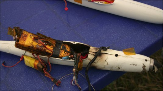
Electrically induced heat... now THERE's something I have first hand experience with taken to the limits. (Lithium polymer BBQ).
11.7v battery & about 150A... that's why we call these flying arc welders, ha-ha
 

Attachments

  • 2017-04-16_10-42-27.jpg
    2017-04-16_10-42-27.jpg
    53.2 KB · Views: 6

PeterT

Ultra Member
Premium Member
These are electric powered RC pylon racers, F5D class. They go about 350 km/hr. 10 laps around a long axis triangular course, its all over in 55-65 secs. These pics were 2008 WC's in Kiev, Ukraine.
My glory days (not so glorious actually).

This was the first year rules required what's called an energy limiter device. It logs volts & current & shuts power off at 1000 watt-min. That was to eliminate the non-limited 'abuse the battery to destruction' era. Kind of like in F1 saying: here is X volume of liquid fuel, go as fast as you can with whatever engine you design. But same catch - if you are set up super fast but run out of electron gas at only 9.5 laps, you'll get passed, so not good. OTOH if you set up more conservative for 11 laps = net slower, left useable energy in the pack, also risk getting passed, also not good. So its about motor wind kV spec-ing + prop tweaking + flying ability & a million other variables that generally drains your bank account. Kiev weather was brutal & very different altitude density.We still managed a 3rd, I have the expensive T-shirts, but have happily retired from all that :)
 

Attachments

  • 3859.jpg
    3859.jpg
    83.7 KB · Views: 5
  • 3851.jpg
    3851.jpg
    40.1 KB · Views: 5

PeterT

Ultra Member
Premium Member
I recently required an electrician/panel specialist quote for a completely different residential job so took the opportunity to have him look at my garage situation. He pulled the cover from my house panel & noted 8 gauge wire feeding breakers/240v to the garage subpanel. (If I heard correct) he said that wire is typically minimum 40A, maybe a smidge more based on wire spec which he couldn't quite make out writing. He said it should be relatively straightforward - come off the garage panel with a short external line to a dedicated wall outlet for welder & new breaker(s) which the sub-panel can accommodate with spare spots. As long as this can accommodate max TIG current draw, I think this is encouraging news.

So what I'm now wondering based on your experience:
- what is a typical cable length included for a TIG welder so I can verify reach vs. where I intend to set up?
- what is the outlet style I should be asking for? He mentioned NEMA 14-50 outlet, Box, 40 amp 240 as an example... but welders can have specific flavors so check first
- with no other 220V machines on while welding, just my 110v ceiling lights, does this sound like sufficient headroom for TIG's like Everlast referenced? I don't foresee myself doing any heavy stuff & my definition of heavy might be 1/4" steel max
- is there anything that can be set on the welder itself to say trip or beep at 35A vs. having breakers trip, or they just don't work that way?
- I believe the garage sub-panel 80A rating is pretty meaningless in this case as the max current is dictated by the house panel delivery (other than the ability to add new breakers in the blanks). Am I correct in this thinking?
 

Dabbler

ersatz engineer
So far I haven't heard the most important fact: What is the rating of the breakers that feed the line to your garage? My Tig and my Mig both require a 220V 50A service. When used in a typical situation (not max power) most mig welders take 30-60% of the maximum current. Thus a 50A service will suffice to run lights and welder in most situations.

I used the common dryer outlet rated for 50A in my shop. That way I could get a relatively cheap (?) RV extension cord to move my welders anywhere I need them, even outdoors. It is no problem and quite inexpensive to recable the welder for these outlets (if they aren't already - my tig, bought much later, already was wired that way)

The 80A rating on your panel is not very telling - only the feeding breakers from the house. That's why I offered to come down and look.

So here is a partial list of things I would check:

1) current requirement for the welder I was interested in buying
2) feeder breaker - which should be 40A for 8 gauge wire, any more is out of code.
3) What load is already on the subpanel, i.e. breaker values, number of loads, etc.
4) overall check to ensure that all wires and breakers are correctly matched for rating and that loads don't exceed.

Regarding the magic of the Canadian Electrical Code and load centres: I have a 60A breaker feeding a 6 ga underground cable to a 100A subpanel, I have 2-40A 220V breakers, 1 50A 220 V breaker and 6 or 7 15 A breakers, all in code and inspected. I never have a problem because the total load never exceeds 40A, even with multiple machines turned on.

BTW I did all the wiring, under a homeowners permit, inspected without any violations.

I hope this helps.
 
Top