• Spring 2024 meetup in Calgary - tentative date Saturday, April 20/2024. Other regions are also discussing meet ups. If you want one in your area get going on organizing it! discussion
  • We are having email/registration problems again. Diagnosis is underway. New users sorry if you are having trouble getting registered. We are exploring different options to get registered. Contact the forum via another member or on facebook if you're stuck. Update -> we think it is fixed. Let us know if not.
  • Spring meet up in Ontario, April 6/2024. NEW LOCATION See Post #31 Discussion NEW LOCATION

Tig vs power panel

PeterT

Ultra Member
Premium Member
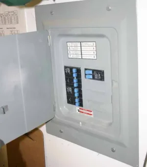
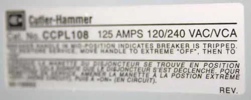
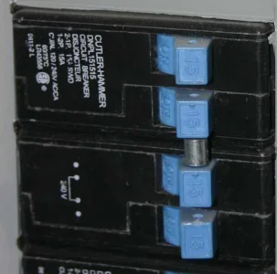
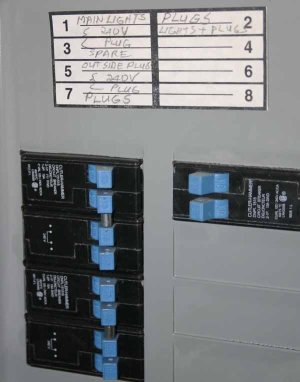
Can someone guide me on suitability of my power panel to a Tig 'one day'. I'm no electrician but guessing I have 2 x 15A breakers dedicated to the 220v outlet my lathe is plugged into, assuming the bar thingy across the 2 switches means 2x15=30A? If so & assuming that's the outlet I plug Tig box into, how do I relate that to current draw the Tig unit needs?

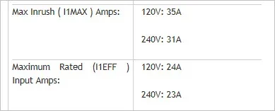
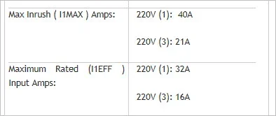
Just as an example, from specs of this unit. Is it the 'in' rating I should be looking at?
220(1) 32A.. means single phase @ 32 Amps? So I'd be 93% ok?
http://www.everlastwelders.ca/tigwelders/powertig-250ex.php

So what would happen if you have under-amped breakers relative to Tig specs? You can still weld at lower power but if you goosed it, the breakers trip? Does that hurt the motherboard delicates?

And I'm guessing that's the max current I can ever put through based on the wiring gauge in the wall & outlet receptacle etc.?
 

Attachments

  • SNAG-4-12-2017 0000.jpg
    SNAG-4-12-2017 0000.jpg
    18.9 KB · Views: 15
  • IMG_5949_edited-1.jpg
    IMG_5949_edited-1.jpg
    46.5 KB · Views: 14
  • IMG_5949_edited-2.jpg
    IMG_5949_edited-2.jpg
    52.1 KB · Views: 17

Alexander

Ultra Member
Administrator
Im also not an electrican but i did wire my whole garage. That is only a 15amp 220 circuit i think? But what size wire do you have there? You need 10awg or bigger if you want to put a 30a breaker in. I had to run another dedicated feed line from the house to the garage just to run my stick welder. The garage is 60 feet from the house so it was about $450 in wire conduit and breakers plus allot of digging to install all that. And now i have 40A circuit for the stick so i can't quite turn it all the way up. It welds fine on the lower settings. I found a chart somewhere on the internet that said how many amps the welder will draw at different settings.
 

Dabbler

ersatz engineer
You do have a 15A 220V circuit, which should be wired 14 AGW You will need to wire it 40A 220V to accommodate the 32A requirement; that means from the fuse panel to the plug needs to be wired as 8 AGW (or 8 gauge if you prefer) I'm not an electrician but have fixed screw ups from licensed electricians for my friends, including fixing 3 phase circuits. Parts of the Canadian Electrical Code used to be on the internet for checking.

I've wired a 50A 220V circuit for my welders and my machine tools use a 220V 40A circuit, 'just because'. My garage feed is 60A 220V.

My first welder, a 'ClarkeWeld' was rated as 120V 20A, but it would still throw a 20A breaker if the wire stuck too long. Sometimes the current rating on the machine is not accurate, so you need a little headroom.
 

PeterT

Ultra Member
Premium Member
This is a dedicated panel in the garage, so power goes through this breaker configuration & into the 220v lathe plug & similar twin into mill plug. So the wiring was done to suit. Its behind drywall but was inspected so I assume whatever gauge wiring was required is in there now. Otherwise why else would they tie two 15A breakers together like that with the pin? I just assumed that gives 30A capability but maybe it doesn't work that way?
 

Alexander

Ultra Member
Administrator
Your correct in thinking
maybe it doesn't work that way?
Its not reall complicated basically 2 wires feed the bars in that pannel with 115v each. The only way to get 220v it to put a breaker across both seperate bars and tie them together for safety just so they always switch off together.
 

PeterT

Ultra Member
Premium Member
Ah, the bar across switches gets me the 220v, has nothing to do with increasing amps? So I only have 15A on my 220v lathe outlet then? Which is about half what the max rated of welder input is if I read specs correct? So any welding above that is an issue?
 

John Conroy

member
Premium Member
I have 30 amp (#12 and 13) breakers set up for my 240 volt plug. I power my lathe, mill and both welders(only 1 at a time of course). AWG #8 conductors from the breakers to the plug. The Everlast tig welder calls for 32 amps but I have never had a problem with just the 30 amp ones.

 
Last edited:

Dabbler

ersatz engineer
Peter: There's a lot of things here... First the bar across only changes you from the 120V nominal to 220V. the breakers say 15A, so that's all you get. To be 100% on your hookup, you need 40A breakers, 220V. I haven't researched your welder, but you can do some careful welding at lower settings, but it is not recommended to regularly cause the breaker to trip. that's a hazard.

May I come over and look at your wiring end-to-end? It could save us from wrong assumptions, etc.
 

Dabbler

ersatz engineer
hey John Conroy, since you never trip the breaker, and your wire is overrated, you shouldn't expect any problem. You might trip the breaker if you go to max current with a high duty cycle, so I assume you tend to be using lower settings. As I mentioned to Peter above, the by-the-book installation is 40A, and the breaker prices is the same (approx). (since you have the correct wire already, you might consider upgrading sometime in the future, but that should require a plug change, unless you used a 40A plug already...)

All the best!
 

Alexander

Ultra Member
Administrator
Standard plugs are 30a and 50a designs. All will be labled somewhere. As dabbler said 8awg should be fine with a 40a breaker so your in luck with wire. I would swap out the breaker with a 40 if your sure it is 8awg
 

PeterT

Ultra Member
Premium Member
Thanks all. Dabbler I might take you up on it but unfortunately not much to see on the wiring, its all behind drywall. I'm guessing the wires start from the panel on one side of garage & go around through the walls to the two 220v plugs on opposite wall where lathe & mill are parked. The initial thought was plug Tig into those but now the 'details' are emerging.

I just grabbed that first welder spec for no particular reason. Just one of the 200 series. Here is another just to compare.
http://www.everlastwelders.ca/tigwelders/powertig-200-dv.php
It shows max rated input current as 23A @ 240v. So am I correct in assuming even with this smaller duty Tig box I'm only good for 15A/23A=65% of what the welder is capable of?
For example they list these typical min/max welding specs so kind of hard to know where I'd land thickness wise, but obviously not full capability if my breakers/line is the limiting factor.
http://www.everlastwelders.ca/tigwelders/powertig-200-dv.php

So what I think I'm hearing is
a) use my existing 220v 15A outlets, but it comes with limitations as above
b) expand the panel & have a dedicated new heavy gage line come off. This might be the easiest thing - maybe just a short, heavy gage in external conduit right adjacent to the panel & plug the TIG in there. I haven't even thought about where I'd set up a welding table but it would probably be a set up / knock down type affair anyway with the space layout I have now.

What I still don't get is how are people doing work on 110v when they don't have 220v with welders that can go either 110 or 220 & same 15A current? I just assumed 220v*15A = twice as much watts as 110v on same 15A breaker & the Tig brain figures out how to turn that into more heat energy. Like an oven or a dryer. Obviously more to welders than I assumed :)
 

Attachments

  • SNAG-4-13-2017 0000.jpg
    SNAG-4-13-2017 0000.jpg
    17.2 KB · Views: 7

Dabbler

ersatz engineer
Given that the max sustained amps are 23, then you can go for 30A circuit. Yes, max inrush is 35A, but that should last for very short intervals (outside the scope of heating wires)

I don't know how efficient your welder is, but I'm guessing it is an 'inverter' type. (the everlast site was down when I tried your links). Assuming that, you are probably in the 70-80% range. This is important because inverters are less efficient in their lower power ranges, or, of you like, produce more heat in the inverter circuit per amp than in the high range. so you won't get 65% of the max amps, probably just under 50%. So if you keep to 90 amps or less, probably you can go with your 15A circuit. I played that game with my clarke welder for a while, but I found it better to just bite the bullet and wire the correct circuit.

What I wanted to check were the actual wires in the circuit (available inside the panel, easy to see), and the breaker feeding the panel. All these have to be sufficient. You can wire a short 30A circuit to a 30A plug on the surface of the wall if it is armoured cable. Since you are buying so little wire the extra cost of the armour is trivial. Flush mount boxes are cheap. and you have lots of room for a new breaker. Good for peace of mind.
 

PeterT

Ultra Member
Premium Member
Ah, I think we have to arrange a panel inspection one day then. I'll lend you rubber gloves & hold the fire extinguisher :)

I don't have a welder, that's kind of why I'm wondering about this stuff in advance. Try this link to Everlast TIG section. Some guys on our forum bought various models & speak well of them so that's just what I pulled for reference. http://www.everlastwelders.ca/tigwelders.php

So on my first pic showing the garage panel, I have 10 breaker switches each at 15A. So does that make it a 150A panel? If so, how does that work if I want to do it right and make a 40A 220v circuit with shorty offshoot conduit/plug for Tig plugin? The line that feeds it is trenched. Are secondary panels like this a max power (wattage?) thing? When we did house renos they turfed the old panel & upgraded but power in was off the main line.
 

Dabbler

ersatz engineer
Could you post a picture of the top of you panel with the master breaker? (If it has one). That would tell me a lot. I'd still be happy to come over and check it out. At least you would know what you will need.

regarding the 10 breaker locations: My garage panel has 32 positions, and I assure you I don't have a 480 amp feeder. I feed this panel with a 60 amp 220v breaker. so it's not just math.
 

kylemp

Well-Known Member
You need to find the brake from the house that is feeding the subpanel. That's your maximum amperage available for the whole garage. That is also the maximum breaker size you can stuff in there although it wouldn't be useful to do that because your breaker feeding your subpanel will also be feeding the lights, etc in there and would kick before the one you installed. Assuming it is 60a, you could go get some wire and throw in a 50a, since that's the larges current plug you are going to find at home depot or something like that which is more than enough.. were running a 350a mig off of 50a and haven't blown it yet. Although we haven't run it at max amperage. We're also running a pretty large tig, either 225 or 275 (can't remember) with no issues on a 50a breaker.
The 50a female plugs are like 17 bucks i believe at home depot and you can get a breaker and wire fairly cheap as long as it's single phase and not a panel from 1902.
 

PeterT

Ultra Member
Premium Member
Some updates. The panel in the garage has no master switch, this is it in its entirety. My house panel that feeds it has 15A&B tied at 40A and 17A&B tied at 40A that both say garage (no pic). So I'm guessing I have 80A to the garage panel? The line is buried in same trench as gas & comes into the garage through a conduit. My 220v plug for both lathe & mill looks like this.
 

Attachments

  • IMG_5957_edited-1.jpg
    IMG_5957_edited-1.jpg
    30.1 KB · Views: 6
  • IMG_5955_edited-1.jpg
    IMG_5955_edited-1.jpg
    45 KB · Views: 7
  • IMG_5954_edited-1.jpg
    IMG_5954_edited-1.jpg
    33.2 KB · Views: 6
  • IMG_5953_edited-1.jpg
    IMG_5953_edited-1.jpg
    28.5 KB · Views: 6

JohnW

(John)
PeterT: It is extremely likely that your in-house panel is labeled incorrectly. One set of 40A breakers is probably for the stove. The other may be for the garage. If you have an electric dryer there will likely be a pair of 30A breakers for that. It would be a very bad thing (both illegal and very unsafe) to parallel two sets of breakers to feed the garage. So, you probably have a 40A 220V service to the garage.

To clear up the whole deal of what happens when you use two breakers to get 220V, you do in fact double the power available. The power is the current times the voltage. So, the power available from a single 15A 120V circuit is about 1800 watts. From a 15A 220V circuit (supplied by two 15A breakers) it is 15A times 240V = 3600W. With a 220V circuit the power comes out from one breaker and returns on the other. So double the power is available.

A standard household service in Canada (and the US in general) is properly called "split-phase power". It consists of two 120V RMS (nominal, sometimes called 110V or 115V) AC lines that are 180 degrees out of phase and one neutral line. Neutral is very similar to ground. The electrical company provides the two hots and a ground to your service entrance. At that point the ground is literally grounded to the ground and from there on the neutral and ground lines continue on as separate things to the breakers and the loads. The neutral should always be very close to ground potential, but can vary slightly when things are under load. The ground line should always be at ground potential. It is there for safety only. Ground lines should never carry current (except when they are doing their safety thing and carrying current to ground because of a wiring problem).

So that leaves you with the neutral (always white), and the two hots (generally black, but sometimes red when dealing with 220V). There is 120V available between either of the hots and neutral and 240V available between the two hots (they are 180 degrees out of phase so they add up to 240V). The breakers are always on the hot lines. That is why there is only one for 120V and two for 240V. Two hots from the same phase are in phase (0 degress out of phase), so they add up to zero voltage between them.

With 120V one line is hot (black), and one neutral (white). The neutral line is very close to ground in potential so it is not really "dangerous". If neutral shorts to ground nothing will really happen in most cases. One hot line varies between ground and +169V. The other varies between ground and -169V. The voltage varies 60 times a second (60Hz). Since the hot lines are 180 degrees out of phase one is high while the other is low so the voltages simply add. When you measure across both hots, it goes from -169V to +169V for a range of 338V total.

Where did 169V come from???? That is the actual peak voltage of the sine wave of the AC voltage. Divide 169 by the square root of 2 (1.414), and you get 120V RMS (Root Mean Square). That is the effective "average" voltage of the line which give you the "average" power that is available. The RMS voltage is what is generally quoted rather than the peak. The peak is always 1.414 times the RMS when the current is a sine wave. This is a simplifications, but it is pretty close to the truth.

Inside the breaker panel: The main bus bars the breakers plug into will alternate between phase-A and Phase-B. A set of breakers placed across two bus bars will have 220V RMS across them. If the two breakers are plugged into the same phase, they will have zero volts across them (there will still be 120V between each breaker's output and neutral). Linking the breakers does not create the 220V, placing the linked breakers across two phases does that. The linking of the breakers is for safety so that if one blows, the other will as well, completely turning off the 220V. Non linked breakers across the two phases will work fine to provide 220V. Note that that does not meet code and is not safe.

There is no problem with oversubscribing within a breaker panel. They are designed for that. When a panel is rated for 60A, it means that the maximum it can be safely fed with is a circuit protected by a 60A breaker (and the appropriate thickness of wire). It is quite normal to have a total of 200A of breakers in a panel rated at 60A and fed by an upstream 60A breaker. If the total current actually drawn by all the circuits in the panel exceeds 60A, it will blow the breaker in the upstream source.

PererT: If your garage is actually fed by a conduit the whole way, it is likely possible to pull thicker wires through from your house panel to your garage panel. Then you could upgrade the house panel to have a 60A breaker, and add a 40A circuit in the garage to feed the hungry 'ol TIG, and still have enough power left over to run the lights and stereo while welding at full power. It is common for the conduit to only go a bit below ground level, then have burial rated wires just buried in the dirt (usually with something like a 2x4 above them for physical protection). In that case, you can't pull new wires through without re-digging the trench.

Did I just completely muddy up the waters, or does what I said actually make sense to anybody???
 

PeterT

Ultra Member
Premium Member
Thanks John. I'll have to check the house panel & see what it turns off. Just looking at my own pic of where the conduit riser enters the garage - is there a chance I have 2 lines coming in (arrows), maybe one to each 40A breaker?.
 

Attachments

  • 2017-04-15_13-03-35.jpg
    2017-04-15_13-03-35.jpg
    22.4 KB · Views: 5

JohnW

(John)
More likely (I would guess), is that you originally had a small service to the garage (probably without a sub-panel) that provided one 120V circuit or maybe two 120V circuits with a common neutral (the same as one 240V circuit). Then a larger 40A circuit was added that feeds the panel. In that case, your house panel would likely have a pair of linked 40A breakers for the sub-panel, and either one single 15A breaker or a pair of linked 15A breakers for the smaller original circuits.

I am assuming that there is only one panel in the garage. It is very likely that the original circuit runs the lights and maybe the original plugs for cars. Remember, most normal people actually use their garages to park cars, and that is when most garages are originally wired for.

If your lights are on the original small circuit, you probably could use a 40A breaker in your sub panel for a TIG. As long as the air compressor does not com eon while you are welding, you would probably be OK.
 

PeterT

Ultra Member
Premium Member
Hmm.. now you have me wondering. The garage was built during my time. Wish I took notes. I told the electrician I'm installing a heater that required a gas line from house & the mill & lathe required 220v. I (foolishly) did not consider a welder in my future. The trench accommodates both gas & electrical, but in terms of 'what' electrical he ran in there I cant say. That's why I was wondering out loud, maybe 2 separate lines? The upper return enters wall at same height as panel box. The lower return near ground level (if that's what it is).. not sure there??. Maybe that controls 110v side, lights & conventional outlets? The coiled black cable is unrelated, I think phone or cable, not used. Do you think instead of one big AWG wire at say 80A he decided to run 2 independent 40's & that explains the 2 breakers on home panel?

Sensing I need someone qualified to confirm & make changes in any event, but just wondering out loud if I'm maybe already semi-knackered.
 
Top