• Scam Alert. Members are reminded to NOT send money to buy anything. Don't buy things remote and have it shipped - go get it yourself, pay in person, and take your equipment with you. Scammers have burned people on this forum. Urgency, secrecy, excuses, selling for friend, newish members, FUD, are RED FLAGS. A video conference call is not adequate assurance. Face to face interactions are required. Please report suspicions to the forum admins. Stay Safe - anyone can get scammed.

Threading to shoulder shenanigans

Interesting interesting. Okay so trust the depth of cut calculations. I have to wonder if some of it isn't related to overall slack and wear too?

I also find I'm getting a burr on the threads as I cut this brass but I have to set back up and check that again.
 
Spring passes do take some material. It depends on the overall rigidity of your setup how much the spring takes. But they are worthwhile to take and improve thread quality in my experience.

To make the clean exit without the relief, I believe @thestelster gave a quick tutorial somewhere as a reply to one of my various posts when I had a large thread relief on the tenon of a barrel. I can’t google search it because it’s obviously in the members only section due to the subject matter.

I’ve followed his method now a few times and it does work. It takes some getting used to and does cause a non-insignificant amount of bum puckering the first couple of times you do it.

The run down:

Set up a dial indicator so that it will start engaging on the carriage as it moves towards the headstock and give you one or one and a half revolutions where you have your “target” measurement, which is pre-set to be about where you want your threads to stop suddenly, with your tool about .100” away from contacting the shoulder yet.

You thread normally towards the shoulder and watch the dial carefully. As it contacts it, you get ready, and when it just hits your target, you quickly disengage the half nut and crank out the cross slide a turn or so at the same time.

One hand on the half nut. One hand on the cross slide hand crank.

You get used to it and can make a very acceptable result. You basically have to use HSS because carbide requires too high of a speed.

This does completely depends on your reflexes. If you aren’t fast enough, Mr whoopees tool will need to be purchased. Or an ELS installed. Or some other method employed.
 
I was expecting some, but this seemed excessive, with how much was coming off after 4 spring passes still !

Currently working with reverse threading.
Your setup is obviously not very rigid. This could be a combination of the lathe, the tool/holder/post, and the work piece. Any stick-out from the chuck especially with a thin ish piece will move more then you think when you cut. Add to that when it isn’t the most rigid material…. Plastic, brass, etc. you could double check your tool is right on centerline, and make sure it is bloody sharp. Usually stoning after grinding to get the final edge is required with HSS.

Reverse threading still needs a relief to get started in. It is less bum-puckery though.

I guess using plastic, you could try the forward method a few times with almost no penalty from missing.

Any “crash” that happens into plastic work piece will leave the lathe, tool, and chuck unscathed as long as it’s stopped before contacting the chuck.

The same cannot be said for running into a 1.125 bar of stainless right up close to a 4 jaw which usually is the case for me.

Give it a shot. Not as scary as you think. Your brain can time the dial pretty well.
 
It maybe an end play thing going on, in hand with some spring back. You are removing tension from the cross feed and the compound on the lathe as you make lighter cuts, this can keep advancing the feed.
You maybe able to check this with a dial indicator mounted on the saddle and the plunger on the tool post, after your final cut to depth and doing spring cuts, see if your tool post is advancing on its own. This also allows you to fairly accurately return to set point of cutter when having backed out of cut at end of thread and maybe easier to see then the dial on the cross feed or compound.
 
I was expecting some, but this seemed excessive, with how much was coming off after 4 spring passes still !
Part of it could be springback in the material, thats normal. The part is held rigidly on one end (chuck jaws) but not supported on the other. The cutting tool is pushing against the part so even if the tool is considered 100% rigid, the part flexes. Analogy is a person standing on the end of a diving board, lots of deflection under the load vs back where its anchored. So another pass at the same DOC setting explains why you typically see fine swarf as the material is slowly relieving itself, coming back to its axial orientation. Skinny boring bars see this too, now you 2 things, flex in the part and flex in the tool. Threads are kind of a special case because you are cutting the face of the thread. Even on the finishing passes shallow DOC the tool is contacting a relatively large oblique area on the of the tool vs any kind of single point cutter. But whatever you are getting on a free machining rigid material like brass would probably be worse on a more flexible material especially if it has more un-equal properties like resins.

A big factor that is largely hidden to hobby machinists is how repeatable the actual DOC setting is. When you make a cutting pass, typically you disengage the cross feed, get back into position, reset the DOC to the exact same position on the dial & re-cut. So you had it set to 0.054" DOC & reset it to 0.054". But is the tool really at 0.054" or maybe 0.053" or 0.055"? Or is it 0.054" but locking the table pushed it to 0.055" Or maybe no table lock is even present on that lathe & its free to drift even more constrained only by the condition of feedscrew + table nut threads which always has some backlash. I cant recall if you set up an independant, accurate gage to monitor this, if so, good thinking. (BTW its not considered good practice to lock the DOC setting & run the threading in reverse to get back to starting position for a variety of reasons).

 
Part of it could be springback in the material, thats normal. The part is held rigidly on one end (chuck jaws) but not supported on the other. The cutting tool is pushing against the part so even if the tool is considered 100% rigid, the part flexes. Analogy is a person standing on the end of a diving board, lots of deflection under the load vs back where its anchored. So another pass at the same DOC setting explains why you typically see fine swarf as the material is slowly relieving itself, coming back to its axial orientation. Skinny boring bars see this too, now you 2 things, flex in the part and flex in the tool. Threads are kind of a special case because you are cutting the face of the thread. Even on the finishing passes shallow DOC the tool is contacting a relatively large oblique area on the of the tool vs any kind of single point cutter. But whatever you are getting on a free machining rigid material like brass would probably be worse on a more flexible material especially if it has more un-equal properties like resins.

A big factor that is largely hidden to hobby machinists is how repeatable the actual DOC setting is. When you make a cutting pass, typically you disengage the cross feed, get back into position, reset the DOC to the exact same position on the dial & re-cut. So you had it set to 0.054" DOC & reset it to 0.054". But is the tool really at 0.054" or maybe 0.053" or 0.055"? Or is it 0.054" but locking the table pushed it to 0.055" Or maybe no table lock is even present on that lathe & its free to drift even more constrained only by the condition of feedscrew + table nut threads which always has some backlash. I cant recall if you set up an independant, accurate gage to monitor this, if so, good thinking. (BTW its not considered good practice to lock the DOC setting & run the threading in reverse to get back to starting position for a variety of reasons).
Fantastic explanation, I appreciate it. I can show my current set up in a bit but yes I'm doing the usual disengage half nuts, back off the cross slide, reset carriage to 0, resent DOC to 0, advance compound slide, and go.
 
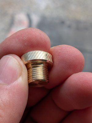
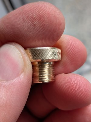
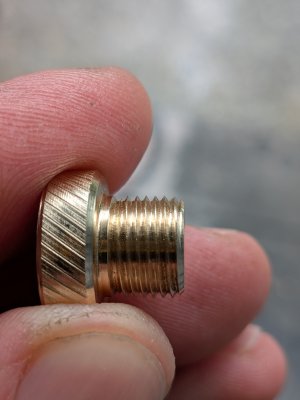
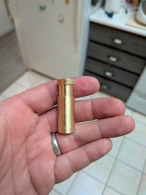
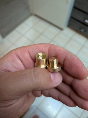
Okay I just finished V6? V7? And I think I am quite happy with this now. Changes were being better about cutting lube, and just doing .002 passes the whole time (no spring pass). I know pictures only show so much, but it seems decent in person.
 

Attachments

  • PXL_20260911_184231022.MACRO_FOCUS.jpg
    PXL_20260911_184231022.MACRO_FOCUS.jpg
    955.7 KB · Views: 7
  • PXL_20260911_184234829.MACRO_FOCUS.jpg
    PXL_20260911_184234829.MACRO_FOCUS.jpg
    914.8 KB · Views: 8
  • PXL_20260911_184248993.MACRO_FOCUS.jpg
    PXL_20260911_184248993.MACRO_FOCUS.jpg
    802 KB · Views: 9
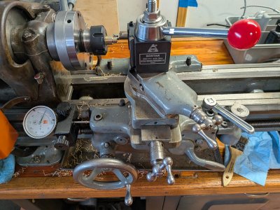
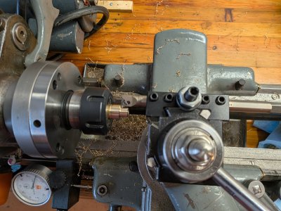
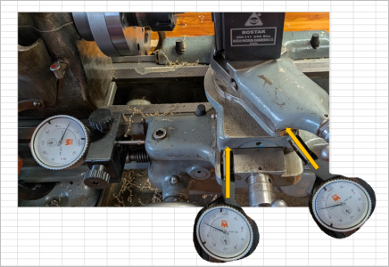
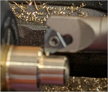
This is the setup I'm playing with at the moment, if it's of interest.

Looks good. What Im talking about is a lie detector gauge in a DOC orientation however you can achieve it. It looks crazy like this because I just cut & pasted your picture to show measurement axis of interest. Straight in perpendicular to the work is pretty easy, some guys have a dial set up like this for normal work on either front or rear of lathe wherever best accomodated. Compound axis is a bit more headache. A DRO on the normal 2-axis makes this issue go bye-bye.

Do you have gib type locks on both compound & cross feed axis? A test you should do for yourself unrelated to threading is hook up a gauge like this just using a mag base or whatever. Then tug the topside toolpost/cutting assembly back & forth with your hands. What does the dial say? That is the +/- float you are likely dealing with.

1789152115900.png
 
Looks good. What Im talking about is a lie detector gauge in a DOC orientation however you can achieve it. It looks crazy like this because I just cut & pasted your picture to show measurement axis of interest. Straight in perpendicular to the work is pretty easy, some guys have a dial set up like this for normal work on either front or rear of lathe wherever best accomodated. Compound axis is a bit more headache. A DRO on the normal 2-axis makes this issue go bye-bye.

Do you have gib type locks on both compound & cross feed axis? A test you should do for yourself unrelated to threading is hook up a gauge like this just using a mag base or whatever. Then tug the topside toolpost/cutting assembly back & forth with your hands. What does the dial say? That is the +/- float you are likely dealing with.

View attachment 86829
Oh boy I KNOW there is a lot of float in both, but good call on measuring it!

There are set screws for the gibs but nothing like a gib lock, if I understand properly.
 
Now I'm looking at this threading tool orientation on the back side of part. I suspect you are traversing from HS to TS probably to avoid issues approaching the HS.

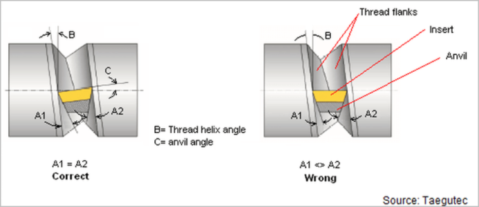
Was this discussed before? On the surface it looks like it should work with a standard internal type insert threading tool, but I dont think so. It is a right hand tool meant to be cutting a right hand helix direction thread internal surface on the surface closer to the operator with normal spindle direction. Its not so much the spindle direction & tool setup, its that the insert may not have the correct profile clearance on the back side of V like you are running it, and the planar tilt angle is set for the intended direction. So threading inward is not the same as threading outward. So I think technically whats required is 1) invert the existing tool, which is probably PITA if not impossible. 2) a left hand tool holder + insert combination (available but less common). Now how much of an issue is it I cant say. But it could well be altering the thread profile a bit and or rubbing. I have similar Chinese thread holders & they dont have any kind of anvil which are used on more industrial tools to tweak the plane of insert. So my guess is they just milled the pocket to some average plane angle, but assume it would only be used in the intended direction. If grinding your own HSS cutter, at least you can manufacture the relief angle aspect.

1789157192315.png1789155435761.png
 
@PeterT without going into too much detail rehashing previous info....

- Yes I am working on threading away from the HS. Frankly I don't know that I'll ever be able to develop the muscle memory etc to do it the traditional way without crashing - at least not in a timeframe I want.
- I am experimenting with both inserts and self ground HSS tools. Right now is still largely about process. If I can actually grind passable tools I'll use them, but at this small scale getting an accurate grind is a challenge for me.
- On the insert front, I find that the internal/bore holders tend to have more clearance around them (at least when considering the inverted arrangement I'm using), making it easier to get very close to shoulder.
- So far I've had the best results with this setup. When I did it the other way (tool upside down, mounted at the front of the work) I was running into complications with the "lifting" force on my carriage assembly.
 
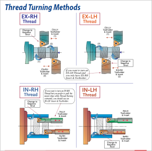
When you look down on an insert, it has the typical 60-deg included angle on the cutting surface face. I think I can safely retract what I said before, the clearance angle under the cutting edge is probably identical on either side of the Vee, at least for smaller thread sizes. I say that because manufacturers actually recommend to infeed perpendicular, not at a compound angle. So from the relief standpoint only, it wouldnt matter if you traverse from right to left or visa-versa.

But there's more to it. The insert cutting plane is inclined at some angle that corresponds to the thread pitch angle, which is there because of the helical pitch. So assuming a flat insert, either the pocket is milled at an angle to incline the insert plane, or its the type of system where different angled anvils (shims) are sandwiched in between. So Left picture is an insert correctly set up feeding from right to left. Right picture is what they are depicting as wrong (for an insert). But worse yet would be Left picture setup traversing from left to right, which I think is the case for the opposite hand tool.

Now a shop ground HSS thread cutter is actually the Right picture. But there you are in control of grinding sufficient relief clearance angle so it does not interfere in direction of interest. But, because its flat top, you pretty much give up any control of rake (relative to the material) angle which is important depending on materials & other factors.

1789174789375.png
 
Last edited:
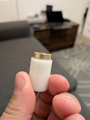
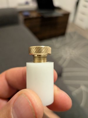
First brass mandrel didn't work so I did a test in delrin to make sure my thread calculations were right. Tolerances are a little loose, but I can go back to brass now.
 

Attachments

  • PXL_20260915_023426561.MACRO_FOCUS.jpg
    PXL_20260915_023426561.MACRO_FOCUS.jpg
    1.1 MB · Views: 4
  • PXL_20260915_023436248.MACRO_FOCUS.MP.jpg
    PXL_20260915_023436248.MACRO_FOCUS.MP.jpg
    1.3 MB · Views: 4
Back
Top