• Scam Alert. Members are reminded to NOT send money to buy anything. Don't buy things remote and have it shipped - go get it yourself, pay in person, and take your equipment with you. Scammers have burned people on this forum. Urgency, secrecy, excuses, selling for friend, newish members, FUD, are RED FLAGS. A video conference call is not adequate assurance. Face to face interactions are required. Please report suspicions to the forum admins. Stay Safe - anyone can get scammed.
  • Several Regions have held meetups already, but others are being planned or are evaluating the interest. The Ontario GTA West area meetup is planned for Saturday April 26th at Greasemonkeys shop in Aylmer Ontario. If you are interested and haven’t signed up yet, click here! Arbutus has also explored interest in a Fraser Valley meetup but it seems members either missed his thread or had other plans. Let him know if you are interested in a meetup later in the year by posting here! Slowpoke is trying to pull together an Ottawa area meetup later this summer. No date has been selected yet, so let him know if you are interested here! We are not aware of any other meetups being planned this year. If you are interested in doing something in your area, let everyone know and make it happen! Meetups are a great way to make new machining friends and get hands on help in your area. Don’t be shy, sign up and come, or plan your own meetup!

Thinking of contacting Klein Tools

Elektrishun

Ultra Member
I know there are some smart electronics people here. Thought I would see if anyone would like to try and hazard a guess as to what is going on with this Klein Tools RT250 GFCI tester.

To help show what is going on I made a Youtube video (see link below).

Keep in mind 4 things:

(1) I am testing a brand new GFCI but I got the same results on installed GFCI receptacles in my house (yet some GFCI receptacles in my house and outdoors tested "good")
(2) Display showing "000" and "OPEN HOT" indicates GFCI is working
(3) Display showing "OPEN GRD NEU" and "> 30V" is obviously a fault but is clearly false (proven false with further testing using DMM)
(4) I already replaced 1 GFCI receptacle that gave me the "OPEN GRD NEU" and "> 30V" result. New GFCI receptacle installed in same location when tested showed "000" and "OPEN HOT"

Youtube video of RT250 testing

Is it the test device that is wonky, or the GFCI that is fuzzing the results, or maybe even user error?

I read the manual.:)

It does state:

NOTE: All appliances or equipment on the circuit being tested should be unplugged to help reduce the possibility of erroneous readings.
I usually interpret "circuit" to mean right back to the panel but that seems kinda silly for a GFCI test.

NO, I DO NOT TRUST THIS DEVICE and will likely return it. Nonetheless, I can't help but be curious as to what is happening with this tester.
 
NOTE: All appliances or equipment on the circuit being tested should be unplugged to help reduce the possibility of erroneous readings.
I usually interpret "circuit" to mean right back to the panel but that seems kinda silly for a GFCI test.
This is a valid point. Many device connected to that circuit will have a small amount of leakage current to ground from stray capacitance and in some cases (Y) safety capacitors. GFCI works on differential current measurement (what goes out the hot should return on the neutral). Any difference is considering fault current. That differential measurement circuit is very sensitive, trips on probably a few ma. So those small leakage currents discussed above even if small they will contribute towards tripping that differential circuit.
 
Last edited:
This is a valid point. Many device connected to that circuit will have a small amount of leakage current to ground from stray capacitance and in some cases (Y) safety capacitors. GFCI works on differential current measurement (what goes out the hot should return on the neutral). Any difference is considering fault current. That differential measurement circuit is very sensitive, trips on probably a few ma. So those small leakage currents discussed above even if small they will contribute towards tripping that differential circuit.

Did you see in the video where I am holding the tester in my hand and after a few seconds the display changes from "OPEN GRD NEU" and "> 30V" to "000" and "OPEN HOT"?

Then when I remove my hand from the device it changes back to "OPEN GRD NEU" and "> 30V". That would be an example of capacitive coupling - correct?
 
I think what's happening is that the input impedance of your tester is quite high and when tripped, your tester is reading 30V. As soon as you add any additional load ( the Fluke), the tiny leakage current that's giving the 30V reading gets snuffed out. You could confirm that by connecting say a 1M Ohm resistor instead of the Fluke. If that's the case, The bean counters at Klein should have not eliminated that 2c part from the design.
 
I think what's happening is that the input impedance of your tester is quite high and when tripped, your tester is reading 30V. As soon as you add any additional load ( the Fluke), the tiny leakage current that's giving the 30V reading gets snuffed out. You could confirm that by connecting say a 1M Ohm resistor instead of the Fluke. If that's the case, The bean counters at Klein should have not eliminated that 2c part from the design.

Appreciate your input.

Screenshot_2025-06-09-11-16-33-25_b5f6883d2c20a96c53babc0b4ac88108.jpg


4.8 stars and over 9000 reviews...
And I'm having this much trouble getting a good test? Crazy.

I did contact Klein Tools. Wait and see.
 
@slowpoke

While I wait for answer from Klein I did a few things:

- checked the battery health of the tester. I have had a meter once give strange readings at work and it turned out the source of the problem was a weak battery. Started labelling the date of replacement on the back of my work meters for future reference. These batteries test good.

- checked the GFCI receptacle that I replaced in my bathroom to see if the reading was still "000" and "OPEN HOT". It was, good test. Previous receptacle kept showing "OPEN GRD NEU" and "> 30V" despite removing receptacle, verifying wiring, and checking for opens in circuit with Fluke.

- checked the voltage of the GFCI receptacle I did the bench test using only my Fluke meter to see if there was in fact any voltage to verify if you might be correct "I think what's happening is that the input impedance of your tester is quite high and when tripped, your tester is reading 30V.".

Using the same power set-up in the video I first checked the voltage with my Fluke to be 120V. Then I tripped the GFCI using the receptacle's built-in TEST button and checked again with the Fluke:

Hot - Neutral = 0.148V
Hot - Ground = 0.717V
Neutral - Ground = 0.263V


Then I disconnected power to the receptacle and took the same measurements again:

Hot - Neutral = 0.030V
Hot - Ground = 0.204V
Neutral - Ground = 0.124V


There is no significant voltage.

For some reason I am starting to believe that the electronics of the tester is interacting differently with the GFCI receptacles circuitry that show the fault. This despite the fact the GFCI is doing what it is designed to do and no issues are found in the power circuit.

BTW, I was getting the "OPEN GRD NEU" and "> 30V" result on newer GFCI receptacles that have the self-test circuitry and older GFCI receptacles that do not.
 
FWIW, I have a few higher end bench DMMs, by default the input impedance for acv is 1 MOhm in parallel with 100pF. This is by design to minimize displayed noise. They also have a mode that switches the input impedance to > 10 GOhm for situations where you're measuring voltages in high impedance circuits and the default 1 MOhm input impedance will influence the measurement. If I switch to that > 10 GOhm range and probe the MAINS circuit (when off) on a device with safety Y safety capacitors I will often get erroneous readings due to the leakage current.

Very curious what results you would get if you connect a 1 MOhm resistor from Hot to Neutral, I'm guessing it will fix your little fidget. If it does you could just add it to your test fixture while you wait for Klein to fix their fidget. Just make sure the resistor is rated for MAINS voltage ie. use a carbon resistor, as many metal film would be marginal voltage wise.

 
Last edited:
Very curious what results you would get if you connect a 1 MOhm resistor from Hot to Neutral, I'm guessing it will fix your little fidget.


Tried your experiment with expected and unexpected results. The expected result was that the 1 Mohm resistor (found a nice 900+ Kohm wire wound resistor in the junk bin) would replace the impedance of the Fluke and influence the circuit in the same manner. Yes, it worked.

Here's what I did:

- set up the bench test as before
- power "on" and used the built in TEST button on the GFCI receptacle to trip it.
- verified with Fluke meter that there was no voltage - GFCI was tripped.
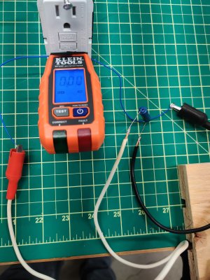
- attached a small insulated wire to the "hot" and "neutral" of the Klein Tools RT250.
- verified that I had continuity from the Klein tester prongs to the bare ends of the wire leads.
- soldered a second set of leads with alligator clips to my 900 Kohm test resistor.

With everything ready to go I plugged in the tester expecting the fault reading of "OPEN GRN NEU" and "> 30 V". Yes, that is exactly what it displayed.

Here's where IMO it gets interesting...

I clipped the alligators to the leads coming off the prongs which were fully inserted into the receptacle. Similar to when I insert the meter or hold the tester with my hand the red indicator light starts flashing for a couple seconds and then the display changes from the fault to showing "000" and "HOT OPEN".

IMG_20250609_192430.jpg


Took it a step further and removed one alligator clip, display continued showing a good test of "000" and "OPEN HOT".
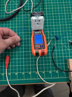
Didn't matter which side I removed. Then I removed both clips, waited for it to go back to the fault display (almost instant), and then grabbed one of the insulated wire leads coming off the tester with my hand. Just like when I hold the tester with my hand, the fault goes away and it shows "000" and "OPEN HOT" for a tripped GFCI receptacle.

IMG_20250609_192827-02.jpeg


I did email exchange with an awesome technical rep from Klein Tools today. He responded very quickly to my questions. A lot of detail as to what could be happening but understandably no definite answers because he is not seeing exactly what I see. No problem. But he gave me a lot to work with.

He did mention the "non contact voltage antenna" in this device. This detail makes me look at this tester the same way I would a volt tick, an OK first check before following up with a quality DMM. He suggested that the electronics in some GFCI receptacles could be interacting with the Klein RT250 in such a way that it is inducing a voltage. When that happens it shows the "> 30V" fault. And I quote from the tech:

"...that whenever the wiring condition is Open Ground Open Neutral, the voltage reading is >30V. This is because there is no ground or neutral to use as a reference point, so the tester cannot measure the magnitude of the voltage detected by the antenna."

So now Klein just needs to add a setting to eliminate "stray voltage" (maybe that 2c resistor slowpoke mentioned...). I finally realize that is the issue. The 1 Mohm resistor, grabbing the tester with my hand, or inserting the Fluke test leads, it's all doing the same thing, grounding the circuit and removing the stray voltage from influencing the test result!

That added feature should now make the $35.00 tester about $100.00.:oops:.

Or just hold it with your hand for about 5 seconds...
 
I made a living as a consultant fixing every conceivable type of circuit. Most of these were large companies that you would expect to have sound engineering practices however the reality is many of these companies have hollowed out their engineering departments for lower cost outsourced options and the results are almost always the same.
 
Back
Top