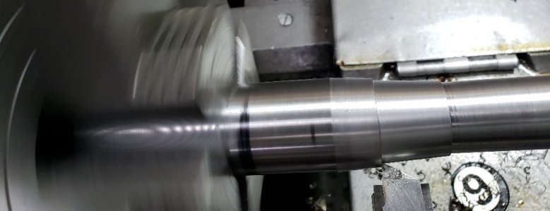
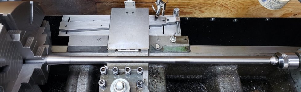
Hi Darren, that is exactly right. Because I'm turning a taper, you can't use a follow rest, so that is what that chuck of steel is for. Without it, it was chattering like crazy. You have to experiment with feeds, speeds, depth of cut, tool bit lead, etc. But this works quite well most of the time.cool video. I had to save and unzip to watch it.
What is the purpose of the block of metal. does that help to mitigate deflection?
-
Scam Alert. Members are reminded to NOT send money to buy anything. Don't buy things remote and have it shipped - go get it yourself, pay in person, and take your equipment with you. Scammers have burned people on this forum. Urgency, secrecy, excuses, selling for friend, newish members, FUD, are RED FLAGS. A video conference call is not adequate assurance. Face to face interactions are required. Please report suspicions to the forum admins. Stay Safe - anyone can get scammed.
-
Several Regions have held meetups already, but others are being planned or are evaluating the interest. The Calgary Area Meetup is set for Saturday July 12th at 10am. The signup thread is here! Arbutus has also explored interest in a Fraser Valley meetup but it seems members either missed his thread or had other plans. Let him know if you are interested in a meetup later in the year by posting here! Slowpoke is trying to pull together an Ottawa area meetup later this summer. No date has been selected yet, so let him know if you are interested here! We are not aware of any other meetups being planned this year. If you are interested in doing something in your area, let everyone know and make it happen! Meetups are a great way to make new machining friends and get hands on help in your area. Don’t be shy, sign up and come, or plan your own meetup!
You are using an out of date browser. It may not display this or other websites correctly.
You should upgrade or use an alternative browser.
You should upgrade or use an alternative browser.
Taper Turning Attachment for Standard Modern
- Thread starter thestelster
- Start date
Now that is cool!!Something I found on Facebook for rifling Kentucky barrels.
View attachment 19958
View attachment 19959
Well the taper turning is done! Now to file and sand while still on the lathe, under power. Then thread, chamber, cut to length and crown, bead blast, and install.
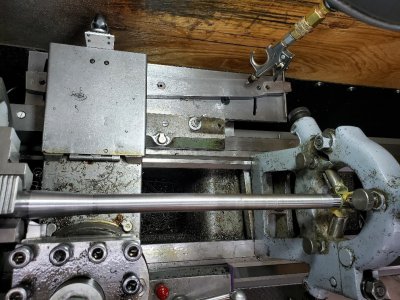
Overall I am extremely happy the way taper turning attachment worked. Absolutely no issues, other than I had to move it a total of three positions to be able to taper the whole barrel. Maybe I should make a taper turning attachment that is 28" in length...(no!!) And by using the sine bar, it gave me perfect dimensions. Two different tapers, 26" of tapered section.
Overall I am extremely happy the way taper turning attachment worked. Absolutely no issues, other than I had to move it a total of three positions to be able to taper the whole barrel. Maybe I should make a taper turning attachment that is 28" in length...(no!!) And by using the sine bar, it gave me perfect dimensions. Two different tapers, 26" of tapered section.
Attachments
I happen to have the same lathe,also without the taper attatchment.Do you have drawings of what you made that you could share?I recently finished up a taper turning attachment for my Standard Modern 16" Utilathe. And it works!! I utilized several different designs which I Googled. Most of the material was from stuff laying around the shop, which means, cold rolled, hot rolled, O1, A2, aluminium.
Hi @Capnkel I do not have any drawings or plans. I basically winged it and used a wood mock up. If you have a look at the pictures in this post, you will see all the items I used. If there are any specific dimensions you want I can measure it for you. Or if there is a specific detail you need, I can take some close up pictures. I have used it quite a few times and I'm very happy with the way it turned out, it is accurate and works wonderfully well. I was going to suggest you drop by and have a closer look if you were in the area, but I see you're in Maine. Welcome. I guess it would be a long drive😳I happen to have the same lathe,also without the taper attatchment.Do you have drawings of what you made that you could share?
Well, if you're ever in the Toronto area, please feel free to drop by.If i was closer i would certainly swing by,its only about 11 hours drive,lol.I,m originally from Yarmouth Nova Scotia.You made reference to a couple plans you found online to help make yours,where might i find those ?
I found a few articles, but mostly pictures from Hardinge, Standard Modern, and several others, and incorporated some aspects of each.
Brent H
Ultra Member
@Capnkel : the standard modern used a very similar taper attachment - all through the lines. I have posted drawings for the original 9, 10 and 12 machines. For the larger machines the theme stayed the same. I will try and post the link to the drawings and some pics of the attachment on your type machine.
This is what the original would look like fitted to a 16” Utilathe.
It looks to me like that taper attachment is only good for 12 inches or so. How difficult would it be to modify it to work over say 30 inches?
Good job. I like the design features you incorporated. So does your particular lathe already have the type of leadscrew that detaches from the main cross slide nut, or did you have to modify that too?Well the taper turning is done!
BTW, what is the caster wheel for?
I'm curious about that too. How do you move the carriage with the taper?Good job. I like the design features you incorporated. So does your particular lathe already have the type of leadscrew that detaches from the main cross slide nut, or did you have to modify that too?
Sorry. I don't get it. On a regular lathe:
The cross slide is moved in and out with a lead screw turning inside a nut that is fastened to the cross slide. The handle and thrust bearing are part of the carriage.
That way you can push and pull on the cross slide and it won't move because the cross slide nut is anchored to the cross slide.
Are you saying the back tray is lifted up un-pinning the cross slide from the nut mechanism?
Hi @jcdammeyerSorry. I don't get it. On a regular lathe:
The cross slide is moved in and out with a lead screw turning inside a nut that is fastened to the cross slide. The handle and thrust bearing are part of the carriage.
That way you can push and pull on the cross slide and it won't move because the cross slide nut is anchored to the cross slide.
Are you saying the back tray is lifted up un-pinning the cross slide from the nut mechanism?
I'm sorry, I've confused you and others for sure. Please go to post #3 of this thread, and it will give you a description of what that casters purpose is.
I think 2 separate things here but @thestelster can confirm. I think the caster is allowing the flap cover to ride up his back splash board & allow for full cross travel, otherwise it could dead end's obliquely.
The disengage-able lead screw is a different issue. Some lathes have this capability but just no taper bar. Others (like mine, grrr..) you have to buy the entire assembly up front. That's why I'm curious if he did a mod.
I have an idea that is would leave my leadscrew intact. It occurred to me when I was mulling a solid tool post. I'm going to mock it up with wood this winter before committing to metal.
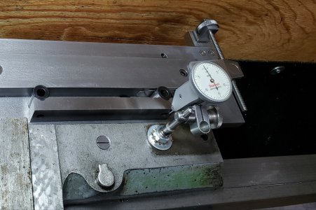
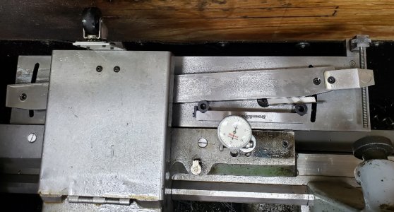
Ah. I get it now.Hi Peter, if you look at a couple of those photos, on the cross slide there is a flat magnet with a number 6 on it. It covers up the hole that a bolt with an oil cup goes into which engages the lead screw nut of the cross slide. The magnet is just there to prevent swarf from getting in. So taking that bolt out allows the cross slide to run freely with the taper turning attachment. I then turn the compound rest which allows me to move in the y axis. Attached to the forward section of the cross slide I made that piece which has 3 holes spaced so that I can accommodate varying diameter round bar.